The Boomsticks


Designer:
Kerry Armes
Project Category:
Tower Speakers
Project Level:
Beginner
Project Time:
8-20 Hours
Project Cost:
$100 – $500
Project Description:
“Yeah. All right, you primitive screwheads, listen up. See this? This…is my BOOMSTICK! It’s a 4″ quad woofer tower, S-Mart’s top-of-the-line. You can find this in the electronics department. That’s right, this sweet baby was made in Ann Arbor, Michigan. Retails for about $299.95. It’s got a MDF stock, brushed aluminum and a hair trigger. That’s right. Shop Smart. Shop S-Mart. YA GOT THAT!?”
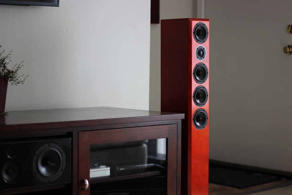
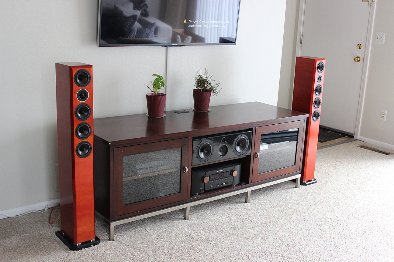
The Boomsticks are a slim, high-WAF, tower design with surprising bass output given the small woofers and relatively diminutive footprint. They utilize the Dayton RS100-8 and Dayton ND25FA.
Design Goals:
I’ve always loved the look of slim “lifestyle” towers that you get in those home-theater-in-a-box (HTIB) systems, but they always perform terribly. If they even come with towers, the HTIB systems typically lack any real bass output, use cheap quality drivers, and plastic enclosures. This leads to localization issues with the sub having to be crossed too high, high, distortion, and resonant enclosures.
I wanted to make something that had a similar look of those towers – slim and sleek with multiple drive units – but performed better in all aspects. I’ve always loved the look of multiple driver towers, and I think most people probably feel the same way about this. I also wanted this design to be good enough for both music without a sub and movies in a HT system with one.
Driver Selection:
For this build, I needed a small driver that could play deep in a relatively small enclosure. However, most small drivers suffer from less than stellar bass reproduction when they can reach low due to high distortion from the small cone trying to reproduce those notes. This is especially apparent as you turn up the volume. After considering a few different options, I settled on the Dayton RS100-8. I went with the 8 Ohm version over the 4 Ohm so that it would have more appeal to people building this design.
There are a number of reasons I chose this driver. First, the outside frame is just under 4” diameter, which meant I could keep the cabinet very slim. Second, the RS100-8 already has low midrange distortion, and adding 4 per side allowed me to lower that even further, reduce the excursion demands at higher outputs, and therefore lower the bass distortion as well. Four of them per side gives you roughly the same cone area as a single 7” driver. You also end up at roughly 85dB efficiency, which is a few dB more than most 7” drivers would be at if used in a standard 2-way. Third, they have a unique set of T/S parameters, that when vented in an oversized box, actually reduces a lot of the excursion demands on the woofer (see excursion graph), again, leading to lower distortion from the small driver.
I knew I wanted a tweeter with a small faceplate to keep the look proportionate and the spacing on the drivers close. I ended up deciding to keep it all Dayton and go with the Dayton ND25FA. This tweeter met my requirements for a small faceplate, it can cross reasonably low, has very good distortion for its price, and a smooth response.
Enclosure Design:
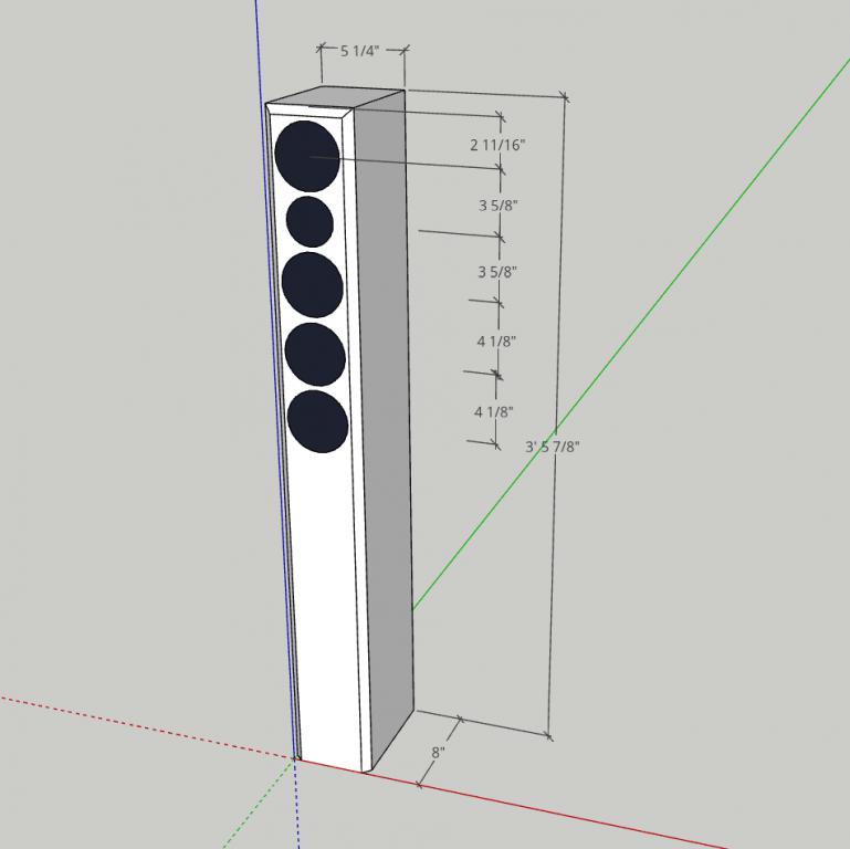
The enclosure was designed to be tall and slim. Dimensions and driver layouts are in the cabinet drawing. I used 3 window pane style braces in the cabinet. Location of the braces is not critical as long as they don’t interfere with the port opening or block driver cutouts. You can use more than 3 if you so desire.
The internal volume of the enclosure came out to be right around 18-18.5L after ports, drivers, and bracing. The cabinet is tuned with two 2” diameter, 7.25” long ports. This gives a tuning around 55 Hz with an f3 around 48 Hz. This provides a fairly satisfying bottom end without the use of a sub.
A single 2” showed vent velocity exceeding desired max at higher output levels which could lead to chuffing. A single 3” PVC looked like it might block the inside of the cabinet too much once an elbow was added for the necessary bend to cover the length.
An access panel was cut into the bottom of the cabinet for the crossover that can reached by removing the base. The aluminum ring around the tweeter is not a necessity and leaving it off will not change the design at all. It was added because I thought I might eventually try the Morel CAT408 in these.
Enclosure Assembly:
These enclosures were CNC cut and shipped to me as a flat pack by forum member Kevin K. but can easily be cut with a table saw or track saw and a router. The only special treatment I did on these was using some Flex Seal on the inside of the cabs to try and deaden the enclosure some. In the end, I found this to likely be a waste of money given the price and the small benefit it seemed to provide in deadening. I would stick with something like flashing paper or car audio CLD material in the future. I could have covered just as much area at a higher thickness for equal or lesser price. The cabinets were then lined in the upper half with denim insulation. I used double thickness right behind the drivers.
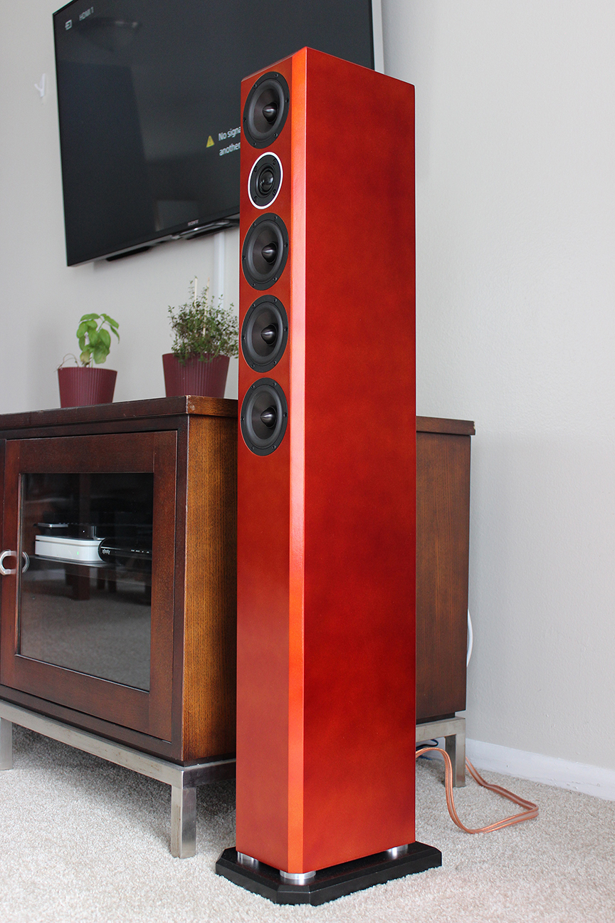
The paint I used on these was Dupli-Color Metalcast. I put down the base coat, which is a light silver metallic flake, and then used a mixture of red and orange of the top coat to get the color I was wanting. I had a difficult time with the Metalcast getting it to go on evenly and it led to some uneven shading you can see in a couple of the pictures. I don’t think I would try this again on a cabinet this large, maybe on a small bookshelf though.
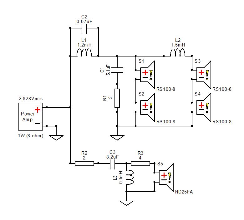
Crossover Design:
The crossover turned out much simpler than I had expected. The woofer section is a damped second order electrical with a bottomless notch and then an additional coil on the .5 woofers. Tweeter is second order electrical with a resistor before and after the crossover. The tweeter ended up roughly second order acoustic at 3200 and the woofers sum to around fourth order at 2700. The RS100 is a small enough driver that this leads to a fairly well controlled off-axis response. For the small capacitor across the inductor in the woofer circuit, I used a 0.1 uF and 0.22 uF capacitor in series with each other and then parallel across the inductor to get the value I needed. A 0.1 uF by itself is pretty close but not exactly where the breakup on my woofer measured.
Tips & Tricks:
You’ll need to plan out the size of your crossover board and layout carefully. Access through the driver cutouts is pretty difficult and even the bottom panel I had on mine didn’t allow much space. A rear access panel might be a slightly better option. As always, I recommend buying a couple resistors of different sizes to play around with the level to taste. On the tweeter circuit, you’ll want to adjust the resistor closest to the tweeter. If have the speakers pushed up against a wall or in corners and feel they are too dark, try reducing tweeter padding and if necessary, go to a slightly smaller inductor in the woofer circuit.
Conclusion:
This design was a fun build and provides for a what I would consider to be a pretty cool little speaker. Honestly, I expected more tradeoffs when going with this format than I had to make in the end. But looking back on how this turned out and considering if I were to build something in a 2-way with a single 7” woofer instead to get roughly the same cone area, my box would be wider, I would have to have a more expensive tweeter that would cross lower to maintain off-axis performance, I would have less sensitivity, I might actually have less cone control on bass heavy material, and potentially more midrange distortion. The only thing I think a 7” 2-way would bring over this design would be slightly lower bass distortion if I were using a higher end driver and a little bit more extension in a much bigger cabinet. But as you can see from the distortion plots, this is still a rather clean design, especially above 300 Hz.
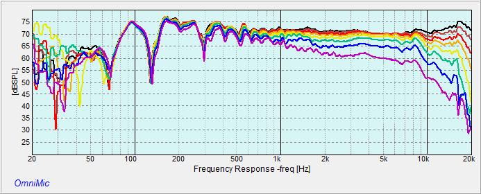
So the real question everyone always wants to know is how do they sound? I’m very happy with them. They measure very flat and sound very neutral overall. Vocals still have a standout quality to them though. That might be due to the very low midrange and up distortion. They image very well, especially with some space between and around the speakers. I’ve also really cranked these to try and get into some excursion issues and I haven’t been able to get the cones moving much at all, even at hearing damage levels. Overall, this is one of the few projects I’ve done where I felt like I not only met my initial expectations, but exceeded them. I really expected more tradeoffs when I first started planning this one out.
About the Designer:
Kerry recently separated from the U.S. Navy after serving 8 years as a nuclear submarine officer. In his time with the Navy, he picked up a significant amount of experience in acoustic and electrical theory. Today, he works as a Project Manager in Ann Arbor, MI. Kerry has been a long time speaker and DIY addict, beginning with car audio in the ’90s. While other kids were trying to get the most “boom” from their cars, Kerry was installing and tweaking his system for maximum sound quality. Kerry got into DIY crossover design in 2012. Since then, he has designed and built around 2 dozen speakers. Kerry focuses on using high quality, low distortion drivers with wide overlap to get the best sound while minimizing the complexity of a crossover. He looks for unique drivers that offer specific benefits for a chosen design to use in a way that maximizes the positive traits and minimizes the negatives. Kerry recently started a website with instructional videos to help other DIY builders learn the basics of crossover design and speaker measurement techniques.
Project Parts List:
I’ve had a couple questions that I wanted to clear up. First, I forgot to add that the entire cabinet was built using 1/2″ thick MDF. Second, the response in the bass is due to room modes from where my measurements are taken. The actual low end response is much smoother, but I did not do a near field merge on the final measurements, only the initial measurements for the sim.
The Dayton RS100-8 is indeed a unique driver with specific benefits. I assume you used them in a series parallel configuration. With good response out to 20 kHz, I wonder what your array of these full range drivers would sound like without the tweeter.
Hi Phil – Yes, the woofers are in a series parallel arrangement. In terms of using these tweeter-less, I personally prefer even smaller woofers like this with a tweeter due to the increased off-axis top end response. Dayton appears to have improved the RS100 aluminum version’s cone some. The last time I used one, the breakup was much larger in both the published response and my measurements. However, I would still probably opt for the paper version if I was going fullrange. It has no visible breakup and should result in a smoother overall sound.
I love the looks of these speakers. Is there a link to the cabinet design diagram mentioned in the text. Can’t find it anywhere in this article
Hi Richard, I’m not sure what happened to the picture. I thought I had uploaded it. You can check here: http://techtalk.parts-express.com/forum/speaker-project-gallery/1325813-the-boomsticks-a-high-waf-slim-tower-with-4x-dayton-rs100-8-and-nd25fa or my website for a full write-up with the cabinet dimensions and more pictures as well. I’ll try to get PE to upload the cabinet drawing ASAP.
I can live with these, that sez it all!
These look awesome, planning on building a pair when I get some time. What center channel is that and are there plans available for it? Thanks
Thanks, Ryan! The center channel is another one of my designs but unfortunately I lost the crossover info when I switched computers. I’m planning on rebuilding it at some point and switching over to matching drivers for the towers (RS150 woofers, RS100 mid, and ND25FA tweeter) but it might be a ways out.
Would love the same principle with 6″ drivers , any suggestions on that or future projects ? Thanks, William
Hi William, I haven’t built any with 6″ woofers and don’t have any plans to at this time. My next build will be a big 3-way with a 10″ woofer. Moving up to a four 6″ woofers per side would require a significant increase in cabinet size, and not just width, but overall volume, to maintain the same bass extension, so it’s a bit of a different build. I’m not sure of anyone who has done a similar build with 6″ woofers to direct you towards.
Kerry, Great design! I wanted to ask you about the finish. I am contemplating doing something similar to my current sealed sub project but using the blue Dupli-color Metalcast. On its own it is far to bright, so my intention was to combine it with the Smoke color to achieve the desired shade. For yours did you simply alternate the orange and red color applications or were you somehow able to find it loose (non-aeresol) for mixing? Also did you use a clearcoat on it? As for the uneven application that you experienced, I am reading that the secret is MANY very light coats (like 5-8) as the color layer is more akin to a dye than a paint and needs to level in low volume. Thanks for any insight and I look forward to more of your designs.
Hi, on mine I alternated the red and orange. I did a couple coats of red first and then a two of the orange, followed by one coat of red. I used the spray cans. I haven’t seen it anywhere that could be put in a gun to mix. I did use a clear coat. You will need to make sure you get enamel for the clear. The Metalcast are apparently all enamel based. Many light coats would probably have worked much better.
For yours, I’ve hear some people have used the Metalcast over other base paints. It won’t look metallic if you do, but you can get it darker and still have a bit of that pearl or candy style paint where it changes color based on the lighting. .
Great job on this very solid build. I was curious when I plugged in your crossover to check out the design the Tweeter was coming in little higher on the decibel. Count when looking at the freq. Response graphs in xsim. Was this by design or did this end up getting lowered I your final design? Or was the Low end brought up naturally to match, that after box res, freq. I see you messurments look,good, it just caught my eye on the freq Response chart . again great build!
Paul,
Thanks for the compliments. I’m glad you like the build. In regards to the tweeter level, are you sure you have the woofers wired correctly in Xsim? When I use the Dayton stock files and the values posted, I actually get a tweeter level that comes in a little lower than the woofer level, not higher. If you don’t have the woofers wired in a series parallel configuration and all files loaded for each woofer, you might see the tweeter showing up about 5 dB too high. For your sim, the woofer level (from around 2 kHz down) should show around 86 dB if summed correctly.
I think I messed up a calculation. Should have tripple checked. Looks good now! I was just at the store today picking up my parts to build something 98% like yours. Thanks for the insperation! These will be my 4th build, and the most solid budget ones I’m about to take on!
Hi
Could you send me the complete drawing of the cabinet? 🙂
Looks cool
Hi Mike,
I don’t have anything further than the drawing posted above. The cabinet was made from 1/2″ thick MDF. The location of the ports and braces don’t really mater much as long as you don’t block any driver cutout or airflow inside the cabinet.
How much damping are you using? Do you have any pictures of this?
I lined the whole back wall and about 1/3 of the side wall with 1″ denim insulation. I don’t know if I have pictures of the cabinets with the lining.
I think its a great idea that you shared on your post.