Top Hats

Designer: mikevv
Project Time: 1-8 hours
Project Complexity: Professional
Project Cost: $100-$500
Driver Selection
To make the speaker design as simple as possible, I chose to go the single driver route. Not only does this facilitate an easier speaker build, it also forgoes the built-in phase and time alignment issues evident in multi-driver speakers. In addition to choosing a single driver, I wanted to use one that was as close to a 4″ outer diameter as possible, because I intended to use Schedule 40 4″ diameter PVC pipe for the main enclosure. I have had great success using PVC in the past, and I also like the “steampunk” look it imparts to projects. I haven’t seen very many designs that incorporate the Dayton Audio RS100-4 in a single-driver application, and I suppose that most would call into account the low sensitivity, but for this design it seemed perfect. Not only does the frequency response extend to 20,000 Hz, it’s fairly linear within its entire operating range (±2.5 dB up to 10,000 Hz). This driver’s motor was also Klippel optimized to ensure that nearly all of its Xmax is usable.
Enclosure Design
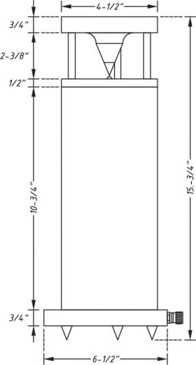
As I stated earlier, I planned on using 4″ diameter PVC for my enclosure (which actually measures 4-1/2″ outside diameter). To hit my small-size goal, and allow the RS100-4 to play as low as the motor and suspension would permit, I decided to make the overall volume of the enclosure 0.08 cubic feet (roughly 2.26 liters), and tune it to 75 Hz with a flared 1-1/8″ diameter by 6-1/2″ long port.
Amplifier/Crossover Configuration
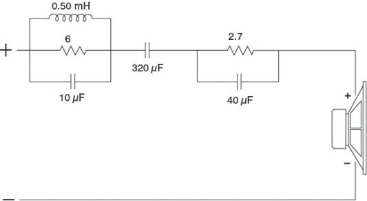
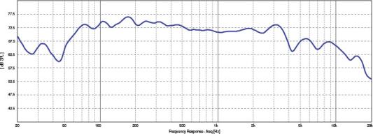
The Top Hat cone design improved the top end response, but not as much as I would have liked. Dispersion was improved, but some degree of upper frequency roll off is inevitable. The easiest way to enhance the frequency response was to employ a wide-bandwidth notch filter that balances the “naturally” omnidirectional lower spectrum with the higher frequencies affected by the Top Hat device. I captured the Top Hat frequency response from about a meter away, using the Dayton Audio OmniMic V2 and saving the output as an .frd file. The impedance response was obtained by using the Dayton Audio Test System (DATS) and saving the output as a .zma file. These files go into Jeff Bagby’s Passive Crossover Designer. The Passive Crossover Designer software is free (though it does require Microsoft Excel) and can be found at this address: http://audio.claub.net/software/jbabgy/PCD.html. For the flattest possible response, I implemented a wide-bandwidth parallel RLC notch filter focused on the 400 to 3,600 Hz band and reducing it to the level of everything above 3,700 Hz. The inductor (L) and capacitor (C) set the band, affected by the resistor (R). All of the components are wired in parallel, and the array is wired in series with the driver. In order to bring the frequencies at and below 400 Hz to this level, I used a series 320 microfarad capacitor, which of course is electrolytic. Since this capacitor is in the signal path going to the driver, you should probably use a bypass capacitor wired in parallel. A side benefit of this particular capacitor is that it raises the impedance of the speaker right at the tuning frequency, protecting the driver from uncontrolled oscillation and over-excursion. The last filter used is called a parallel RC contour filter. Its job is to shape the overall response. If you plan on building these the exact same way, you can tweak this section of the circuit to tune the speaker to your own personal taste. You can dial in more bass by reducing the value of (or even removing) the resistor. For the best possible output without the use of filters, one could use plaster or a lathe to create a very seamless transition. I would highly recommend plaster as you will likely have to go through multiple iterations to find the best possible shape.
Enclosure Assembly
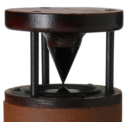
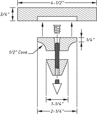
Using a hack saw, I cut the PVC to 10-3/4″ long and then painted the tube with brown “stone fleck” paint. Mounting the driver and port requires the use of mounting rings. I had some very nice 3/4″ oak lying around and knew that using it would only make this speaker look better. Using my handy router and “Router Buddy” attachments, I cut a 4-1/2″ O.D. circle to match the PVC’s diameter. Before I cut the driver hole, I flipped the circle over and cut a 1/4″ rabbet to create a lip to mount the ring to the tube. Once I was happy with the fit, I cut the driver mounting hole that I also recessed so the driver would be flush with the surface. I then predrilled all driver mounting holes and used Red Oak stain to finish the ring. The bottom ring also doubles as the speaker stand. I cut a 6-1/2″ O.D. circle, trimmed a 3″ flat area to mount my binding posts, and cut a 4-1/2″ diameter circle that was only 1/4″ deep. I then repeated this step while reducing the circle diameter to create a 1/4″ deep opening for mounting the PVC tube. The port tube mounting hole was then made in the center. Using a drill press, two 1/4″ holes were drilled on the flat end to mount the binding posts and run the wire to the inside of the tube. Finally, I mounted three screw inserts on the underside for mounting the spike feet. The bottom ring was also finished using a Red Oak stain. After the stain and paint dried, the rings and PVC tube were glued together. The hardest part of this particular design (and where its name came from) was converting the high frequency output of this driver from directional to omnidirectional. The driver is omnidirectional at frequencies where the wavelength is physically larger than the driver and mounting ring. The speed of sound in inches is 13,512 inches per second (this is a rough estimate as it changes with temperature and barometric pressure/altitude). The outer diameter of the pipe is 4-1/2″, so 13,512 divided by 4.5 equals (roughly) 3,003 Hz—very close to the corner frequency at which the high frequency response starts to drop as the output becomes directional. I began looking through the Parts Express catalog and noticed that the Dayton Audio DSS4-BK spiked foot not only gave me a starting point (pun intended) to work with, it also matched the look of the RS100-4’s cone and phase plug. Using another piece of 3/4″ oak, I again cut a circle 4-1/2″ in diameter. I then cut a 2-1/4″ diameter circle only 1/4″deep. I repeated this step while reducing the circle diameter to create a 1/4″ deep opening in the center. Another piece of oak was then cut in a 2-1/4″ diameter circle. Now here is the tricky part: using a 1/2″ cove bit in the router, gently remove material to form the upper part of the cone. The “cove” should start at the surface of the material, which will leave 1/4″ at the bottom for the router bit bearing to ride on. You will have to secure the 2-1/4″ diameter material so it does not go flying across the room. Then all you need to do is mount a screw insert for the lower end of the cone and glue the upper and lower pieces together. To mount the “top hat” I used three #12 x 4″ screws. These fasteners went into the driver mounting hole locations. To dress it up, I used painted aluminum tubing from target arrows purchased from a local sporting goods store cut to 2-3/8″ lengths. I then installed Acousta Stuf, wired the driver, and mounted it in place.
Conclusion
I really like the look of the Top Hats! They have a neo-industrial appearance that complements nearly any desk or room, consume very little space, and can be used almost anywhere. They are attention-getters. I’ll be using these as desktop speakers, so I have adjusted the speaker height to ensure the opening between the driver and waveguide aligns with my ears when I’m seated. This is a good thing to keep in mind, and if you choose to use these as mini-main speakers, you would be best served by using 24” speaker stands. For background and surround sound use, this is less of an issue. The sound of omnidirectional speakers is something you have to hear if you are into audio. When properly placed, they impart a spacious sound that is almost other-worldly. A friend once told me that they are the closest of any speaker design at getting the binaural sound of headphones into your head. I couldn’t agree more. Enjoy!
About The Designer
Mike Van Den Broek has been an electronics enthusiast all of his life. Mike’s designs reflect a desire to stand out from the crowd, yet draw listeners in with the sound. Unimpressed by what he has seen in the retail audio industry, Mike prides himself on his ability to make speakers on his own that not only sound better, but also cost less.
Project Parts List
|
Part # |
Description |
Qty |
|
295-378 |
1 |
|
|
091-1247 |
1 |
|
|
260-472 |
1 |
|
|
240-664 |
1 |
|
|
027-442 |
1 |
|
|
004-2.7 |
Dayton Audio DNR-2.7 2.7 Ohm 10W Precision Audio Grade Resis |
1 |
|
027-372 |
1 |
|
|
255-036 |
1 |
|
|
004-6 |
Dayton Audio DNR-6.0 6 Ohm 10W Precision Audio Grade Resisto |
1 |
|
027-340 |
1 |
|
|
240-717 |
1 |
|
|
260-317 |
1 |
+ There are no comments
Add yours