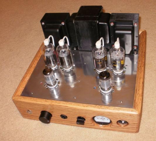
True Compactron Tube Amplifier


Designer: Nanook
Project Time: 20+ hours
Project Complexity: Hobbyist
Project Cost: $100-$500
Overview
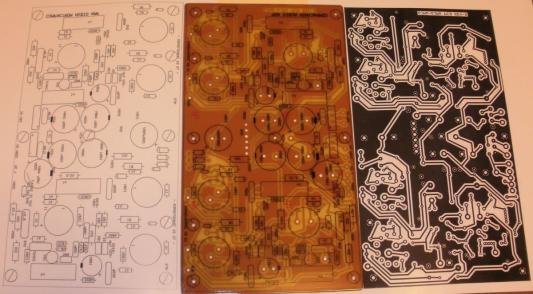
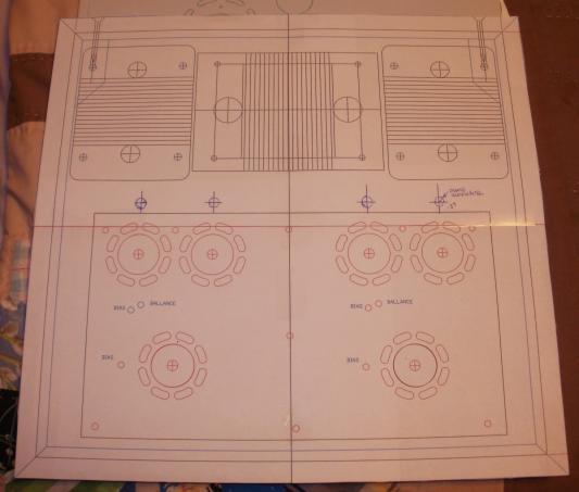
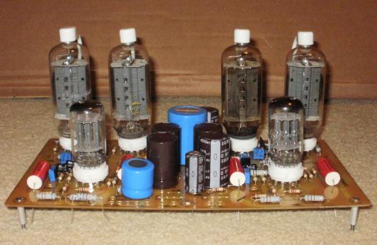
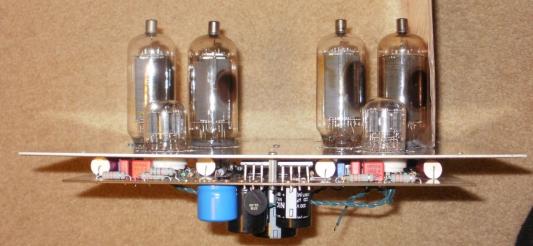
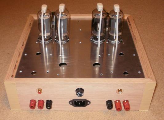
Compactron line of tubes was GE’s last stand for tube that defended their position against the onslaught of solid state devices. GE removed as much cost to manufacture as possible where is some cases they placed 3 tubes in one case. The design of the amplifier was inspired by the work done by O.H. Schade of RCA in 1938, P.Millet and D. Berning with their work on using TV tubes from the 60’s and designing them into audio power amplifiers. I decided on a design that used all Compactron tubes because they were cheap, thus a True Compactron Tube Amp design. The 6U10 was like a combination of a 6AX7 with a pair of 6AU7’s, one high gain with two medium gain tubes. I have the high gain for the first stage and the two medium gain tubes for the long tail pair second stage phase splitter that will drive the power tubes. There are several other triple triodes that are pin compatible for tube rolling. The output tubes selected are the Compactron horizontal deflection coil driver tubes from B&W and color TV’s. For a great picture the output from the tubes must be very linear, thus they should be very linear in an amplifier application. There are a couple different groups of tubes, 18 watt dissipation and their larger brother’s 33watt dissipation. You can also find the larger tubes in the output sections of tube ham radios. As far as the design goes the deciding differences between using the two groups is the amount of heater current required and the negative bias voltage needed to control the quiescent current. This will influence the power transformer requirements. The larger tubes require a lower negative grid bias to control the quiescent current to the 40 to 50ma range and due to the larger cathode and plate areas. If needed, additional 6.3 volt heater transformers can be added to supplement this requirement, or in the case of using 36KD6 output tubes additional 36volt transformers can be used. For a 30watt amplifier/channel the smaller 6JN6, 6JM6/ 6GV5 tubes will work, for a 60watt amplifier / channel the larger tubes will be required. The first amp was designed to be in the 30 watt/channel range so 40 watt Hammond iron was chosen for the outputs. For the largest version, the 6LB6 tubes along with 60 watt Hammond iron was chosen. The voltage rating of the filter capacitors will limit the B+ to around 400V and if stacked you can increase it. Electrolytic caps can be found in the 450V range with fewer and more expen$ive ones in the 500Volt range or even higher. I decided on a PCB based amp instead of point to point wiring. The power supply is placed in the center of the PCB placing each amplifier on the sides. The single sided PCB is designed and printed out onto standard letter sized paper and edited with whiteout and black gel pen. The completed design is “copied” onto high clay content paper with the contrast set to try to get the largest toner build up without starting to fill in between the traces. The toner is ironed to the copper after cleaning it with steel wool to remove the oxide layer. The paper is removed by soaking the PCB in cold water for ½ hr to allow the paper to fall apart. It is carefully rubbed off leaving the toner and a thin layer of clay from the paper melted to the copper. This layer acts as etch resist and any damaged spots can be touched up prior to etching. I use Testers modeling enamel and a fine pointed brush for those little corrections. After etching, the toner is removed with a solvent, the copper is steel wooled to clean it and “liquid tin” is used to flash plate the copper to protect if from oxidation. The top side silk screen artwork is done the same basic way as the back, except for using lava soap to just remove the clay from the top of the toner so the artwork will be a high contrast black. The final protection is a top coat of clear spray enamel. A Dremel tool with fine burr drills will make short work of the component mounting holes. I do all of the holes with the small burr and then modify the holes as needed to mount the components. The tube sockets require a little slotting and the holes for mounting the capacitors on the back side and all wire mounting holes require enlargement for the grommets. I mount the completed PCB on standoffs and start stuffing the components for a mounting check and look for components that I still need to scrounge. The chassis is designed after the PCB is finalized. I needed to mount the PCB to the underside of the aluminum top plate. All of the mounting holes, tube holes and pot adjustment holes were deigned into a CAD layout. The transformers were chosen and added to the layout. Transformer position and mounting angle is important to prevent cross coupled interference. This determines the final footprint of the amp and the available space on the front and back panel. The top layer design is spray glued to the aluminum sheet and the holes and slots are machined into place. I like to put vent slots at the tubes for a little cooling action. The holes need to be counter sunk for the mounting screws and the tube socket holes need to be enlarged and trued to position. The slots get the burrs filed and then the entire top gets a good buffing with polish for an improved shine. The ¾” thick wooden chassis is designed for the top and bottom layers to slide into place, ¼” deep kerfs are used. The design is 3 sided with a removable back. For mounting of the switches and other hardware both front side and back sides of the chassis are drilled and milled out for the proper mounting thickness and clearances. All parts are fitted prior to the glue up and dreaded sanding marathon. I chose a light stain to match my oak speakers followed by 8 coats of tung oil finish. The assembly process is simple, mount all hardware to the front and back chassis panels and transformers, choke and PCB to the top plate. The design was up and running, all voltages confirmed and biases were tweaked so we just slide the top plate into the chassis and complete the final wiring. Be sure to add a fuse and connect the chassis ground. Install the tubes in the same positions and connect to speakers and input, I used a MP3 player. DO NOT fire it up without a load on the output, high voltage inductive spikes could breakthrough the winding insulation and short out the transformers! Confirm hookup and fire it up. Watch the bias levels on the output tubes and after stabilization adjust them all to 40 to 45 ma, matching as close as possible to prevent core saturation due to current offsets. The dissipation of the output tubes is .040A x 380V= 15 watts, just under their rating. For the larger amp, .050A x 550V= 28watts under the 33watt rating A year later, the little amp is still my favorite over other amps including a ST-70 clone. I’m surprised by the clarity and soundstage that it presents. Tube life should be in the 2,000 to 5,000 hr range so I have a small stash of replacement tubes to keep it running for the years to come. For more information and inspiration on tube amplifiers, check out the forums on the net. Check out Parts Express for their parts availability for your next amp project. There are so many design possibilities, just limited by your imagination and investment cost in time and effort.
About The Designer
Schooled at DeVry, work experience includes linear design and characterization at National semiconductor, Digital at Intel, Hybrid circuit integration at Cermatek, Analog circuit designs at Honneywell, Space Flight Electronics at TRW/CE.
Nice Job. PCB must have been time consuming. Built many tube amps in the 70’s when we had the Harmon Kardon boat anchors and Dyna Kits, etc. I have to question your cost estimate using new ? Hammond transformers. They are extremely costly. I used less expensive transformers like Stancor in the 70″s unless I could salvage some McIntosh. The outputs used both cathode and plate windings, hence the name “Unity Coupling”. By allowing the plates and cathodes to float, they achieved 1/2% THD..
Some high power amps I built for circus and carnival use had up to 8 push pull 807’s for outputs. The only drawback was trouble shooting a chassis with 800 VDC everywhere. I really love the sound of tubes with plates flickering, pushing hard. I still have my Mac equipment from ’72 in perfect working condition after 1 refurb.. I think it will outlast me , in my 70’s Good job, liked your project.