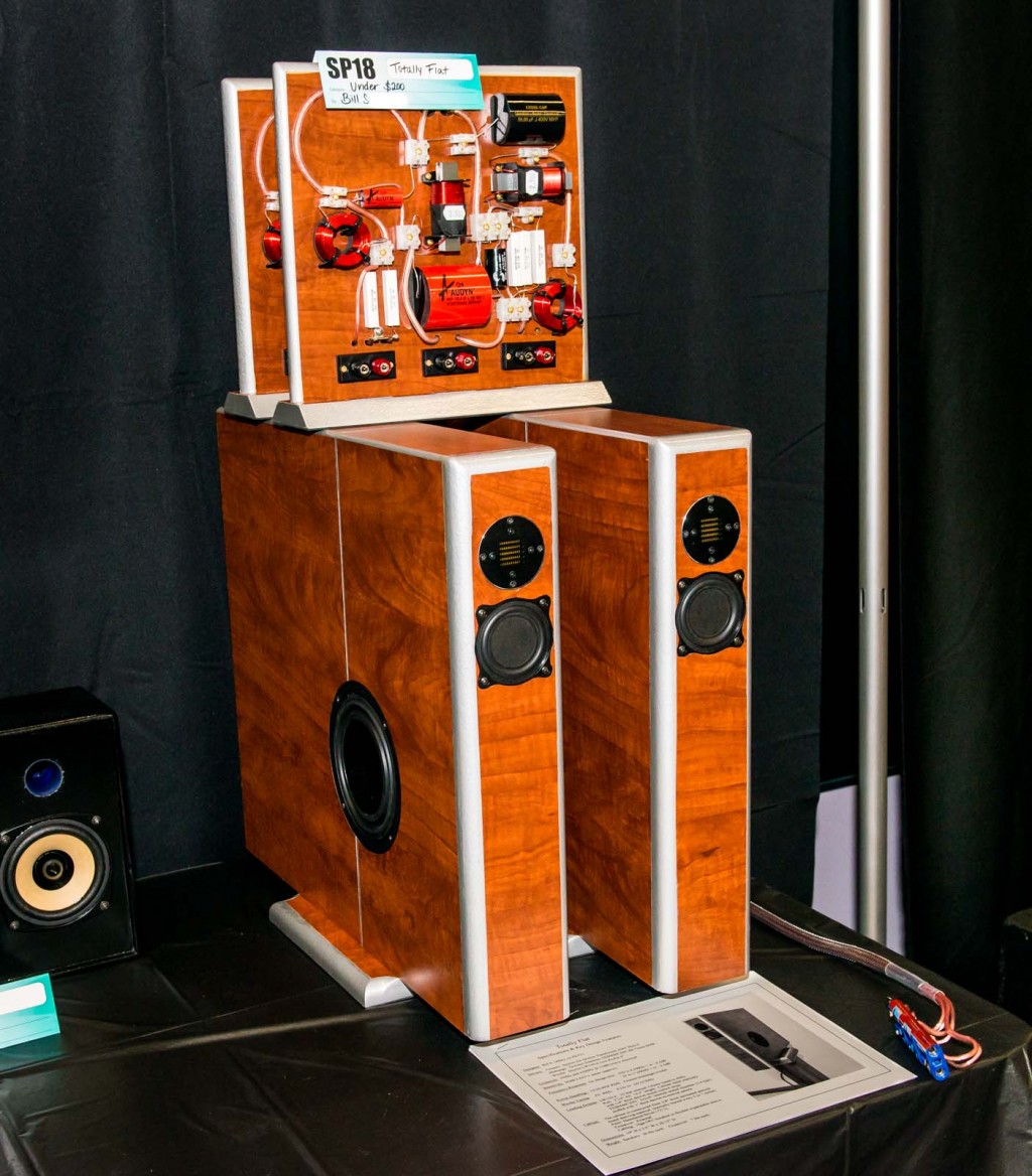
Totally Flat
Designer:
Bill S. (4thtry on PETT)
Project Category:
Bookshelf Speakers
Project Level:
Intermediate
Project Time:
20+ Hours
Project Cost:
$100 – $500
Project Description:
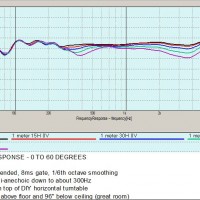
This is a super thin, 3 way loudspeaker with excellent imaging, very flat frequency response in the mid-range, and a very broad and uniform horizontal and vertical polar response pattern. It uses the full 6dB of baffle step compensation and should be placed on a 24″ high speaker stand and be located well away from the rear and side walls of a moderate to large sized listening room.
Design Goals:
My goal was to design the best sounding speaker that I could without exceeding $200 for all drivers. I wanted it to be capable of at least 95dB SPL at 1 meter with good low frequency extension to 35Hz. Stable imaging and 3D sound-staging were extremely important. The speaker must also have good high frequency extension, clarity, or “air” without harshness in the mid to upper treble region. Finally, the speaker must have a very neutral tonal balance from the mid bass up through the lower treble region (350 to 4500Hz).
Driver Selection:
Tweeter: I selected the Dayton Air Motion Transformer AMT Mini-8 to keep driver cost down and to meet my goal of good clarity and “air” without harshness. The crossover point, however, must be kept very high when using this particular driver.
Mid-range: I selected the Tectonic Elements TEBM46C20N-4B 75mm Balanced Mode Radiator (BMR) to keep driver cost down and to meet my goal of a very neutral tonal balance from 350-4500Hz. I have used this driver before and find that it has a very flat and smooth sounding response throughout the mid-range and lower treble region. It seemed like the perfect match to the AMT Mini-8, which needed a very high crossover point. In addition, this driver has a very broad and uniform horizontal polar response that is very similar to the tweeter. With close driver placement, I felt that I should be able to obtain excellent horizontal & vertical polar response.
Woofer: I selected the Dayton LW150-4 low profile 6” woofer because the cost was low and I needed a shallow driver for side mounting on a thin cabinet. Based on my experience, I have found that a very thin baffle is needed to meet my design goal of excellent 3D sound-stage imaging. The LW150-4 fits my design criteria perfectly because it is only 1.5” deep and can be tuned quite low in a very small cabinet.
Enclosure Design:
Internal cabinet volume is approximately 10 liters. External dimensions are 19” H x 3.5” W x 20.75” D. Material is 3/4” laminated particle board shelving throughout. I created the port by simply gluing in a 15.5” x 2” partition, 2.75” forward from the rear of the cabinet, leaving a 2” opening at the bottom for the port exit. The port therefore has an inside diameter of 2” x 2” and is 16.5” long (Fb: 40Hz). I lined the cabinet internally with 1/4” thick dacron. I used several small 1.5”x 2” side to side braces to stiffen the side walls. I supported the speaker on the bottom with a 6×9″ base board.
I located the side mounted woofer 11.5” from the top and 7.5″ back from the front of the cabinet. This places the woofer at the golden mean ratio (1.62 to 1) which helps to spread out internal cabinet cancellation and reinforcement modes.
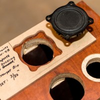
I gave the mid-range a small, sealed sub enclosure that measures 2”x 2”x4” internally and constructed it from 1/4” thick HDF material. I stuffed it with two layers of 1” thick dacron. I located the mid-range cutout 5.75” down from the top of the cabinet, on center. I positioned the tweeter cutout 3” down from the top of the cabinet, also on center.
Enclosure Assembly:
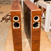
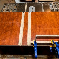
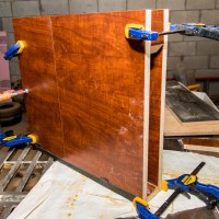
I used miter joints on the two sides and top to create a smooth, hidden top seam. The baffle board is 3.5”x 18.375” and is surface mounted with yellow wood glue. The 2”x 15.5” rear panel is inset into the cabinet’s back and is open on the bottom for the port exit. The sides are 18.5” x 20” and are mitered 45 degrees along the top edges. The top is 20” x 3.5” and is mitered 45 degrees along both of the long, top edges. I used gaffers tape to hold the two sides and top together, filled the miter joint with glue, and then folded & clamped the composite into the shape of a very flat box.
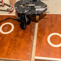
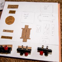
I flush mounted the woofer, mid-range, and tweeter using custom templates and a router bushing set. This keeps the plane of all drivers totally flat with the plane of the baffle and the plane of the side walls. To soften the baffle step, I used a 1/2” round over bit to ease the baffle edges. I used a 1/4” round over bit to ease the top two edges. After finishing and sanding the edges, I painted them with a single rattle can of Hammered Silver (#7213).
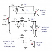
I built the crossover externally on a 12″ x 11.5″ piece of 3/4″ laminated particle board, mounted vertically to a 12″ x 3″ base. It is connected to the drivers via 6 individual runs of 16ga OFC cable, bundled inside a 3 foot length of Techflex expandable sleeving. I connected these cables individually to the crossover board using 3 sets of stereo banana jacks. This gave me complete access to all driver terminals at the crossover so that I could easily re-do any botched measurements or flip the phase to examine reverse nulls.
Crossover Design:
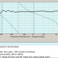
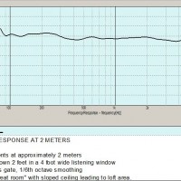
After finishing the cabinet and mounting all drivers, I used OmniMic and DATS V2 to create a complete set of on-axis FRD and ZMA files that included baffle step and floor boundary reinforcement gain. Since my “in room” measurements are only quasi-anechoic down to about 400Hz, I applied 1/3rd octave smoothing below this frequency to create files that were very close to quasi-anechoic down to approximately 100Hz. I then loaded these raw FRDs into the XSim software package, set the mod delay offsets, and developed the crossover
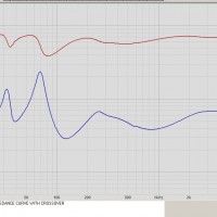
I set the tweeter to mid crossover at 4.2kHz, 12dB per octave electrical. I set the mid to woofer crossover at 350Hz, 12dB per octave electrical. XSim is a very easy software package to use, allowing the user to quickly adjust part values and/or swap parts in and out on the fly. In very little time, I had a simulation that measured + or – 0.5dB from 350 to 4500Hz and roughly + or – 2.5dB from 35 to 17000Hz. Impedance dipped to roughly 3 ohms at 125Hz but the phase angle was roughly 0. Any amplifier capable of driving a 4 ohm load should have no problems with this speaker. Overall sensitivity was approximately 85dB/2.83V/1 meter.
Conclusion:
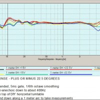
This was a fun project. Flat cabinets, flat drivers, flat mountings, flat crossovers, and a reasonably flat frequency response as well, both on and off axis! All in all, a very good sounding speaker for the price. And I can listen to this speaker system for hours without fatigue. The AMT Mini-8 gives the mid to upper treble region a special clarity, depth, and “air” that blends well with the smooth and very neutral sound of the TE 75mm mid-range.
About the Designer:
I have been building speakers and amplifiers, as a hobby, since the mid 1970’s. In my spare time, I enjoy football, fishing, camping, landscape photography, building amplifiers, and, of course, building speakers. I also enjoy attending the many DIY events in the Midwest to see what other speaker builders are up to. I do not have a formal degree in electronics or engineering. Instead, most of my skills have come from reading detailed construction threads posted on the PETT forum.
Project Parts List:

Excellent work. Love the design and the low cost. Could a electronic crossover be used with similar results? It would make it alot easier for me.
Thank you
I see no reason why an electronic crossover could not be used to save time & money. However, I prefer the sound of a high quality passive type xover.
Thanks. If you have the ability to duplicate my passive crossover electronically, I can see no reason why this could not be accomplished.
Bill