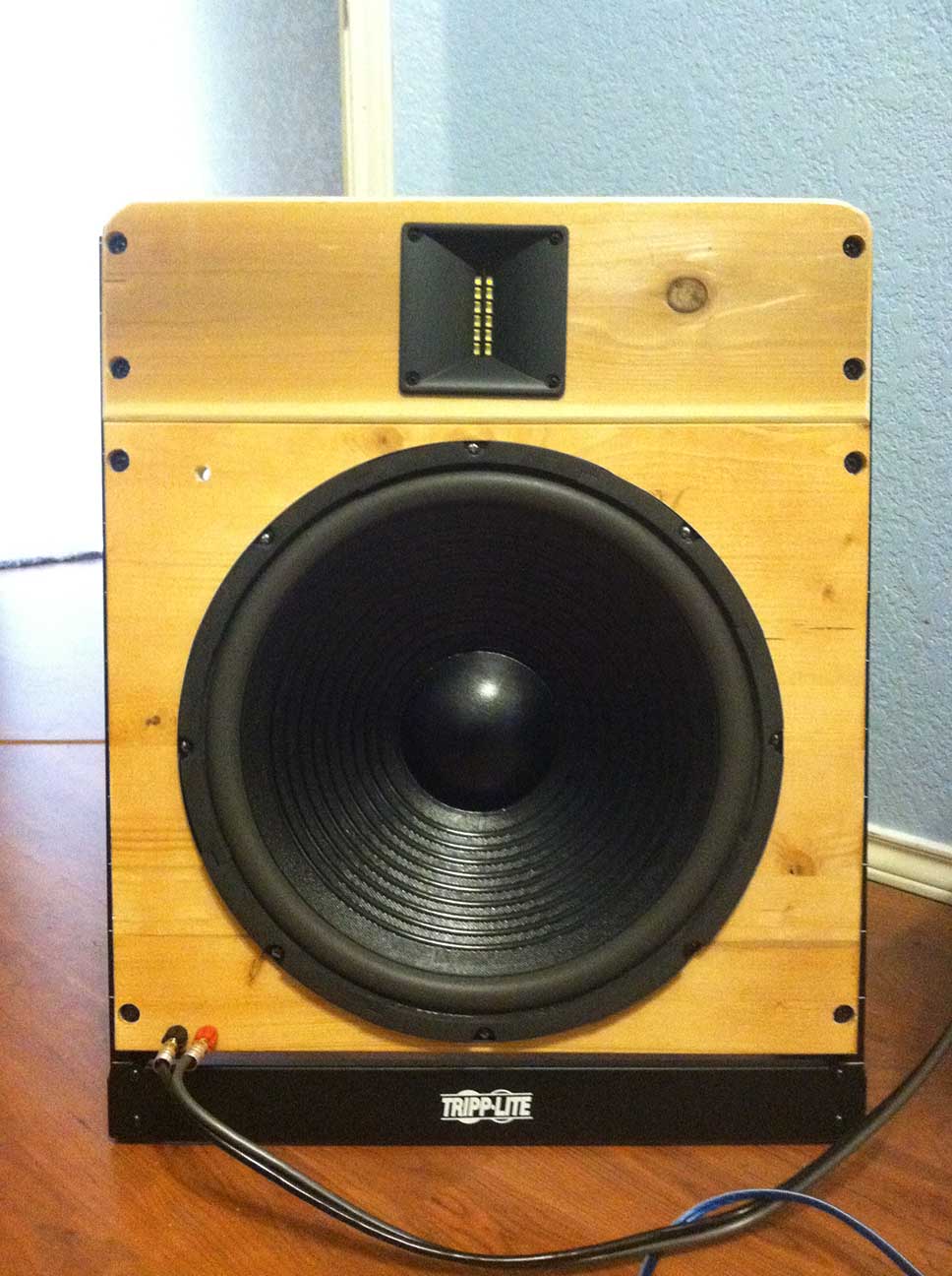
A 15” Full Range Open Baffle
Designer:
Craig J. Coley
Project Category:
Loudspeakers/Cabinets
Project Level:
Beginner
Project Time:
1-8 Hours
Project Cost:
Under $100
Project Description:
This project is called the Coley OB15 Open Baffle Speaker. It is a full range speaker with a manageable baffle size and integral electronic compensation for baffle losses. In addition, the impedance curve of the speaker presents itself as a light resistive load at high frequency, making it a good match for single-ended triode amplifiers with little or no negative feedback.
Design Goals:
This project began as a desire to experience the transparency of an open baffle but with full range performance. Limited space meant limited baffle size so it was known from the beginning that compensation would be required. A theoretical efficiency loss of 10dB was deemed acceptable so long as the response was reasonably flat and extended to at least 50 Hertz. In addition, it was desirable to drive the open baffle with a single-ended triode (SET) amplifier. Since it is common for SET amplifiers to use little to no negative feedback, the open baffle impedance needed to remain at 8 ohms or greater at high frequency since amplifier impedance stabilization caused by negative feedback would not occur.
Driver Selection:
While some efficiency was willingly sacrificed to obtain a wide frequency response, these losses can become excessive in the last few octaves below 100 Hertz. To minimize these losses, a large woofer was sought with a higher Qts in the 40 Hertz range but not so excessive that a noticeable hump would be created in the response curve. The Goldwood GW-215/40/8 (P/N 290-346) with a Qts of 1.087 around 40 Hertz met these requirements at a very modest price. The tweeter selection was based upon the desire to have high detail and transparency along with dipole characteristics. The Beston RT002A (P/N 277-116) ribbon tweeter met these requirements with a wide, flat frequency response, and at a very modest price.
Enclosure Design:
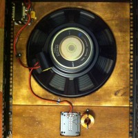
As an open baffle prototype, the enclosure consisted of nothing more than wooden panels for each speaker driver mounted to a desktop rack. An edge glued pine panel of 19x16x0.75 inch was used for the woofer and a cedar panel of 19×5.5×0.75 inch was used for the tweeter. Edges of the panels were finished with a router and round-over bit. The 0.75 inch thickness of both wooden panel types allowed easy mounting of components to both sides of the panel but does require countersinking of the rack mounting holes. Because solid wood is used, predrilling of holes is mandatory. MDF would be a better choice for most builders but was not a choice here due to people with formaldehyde sensitivities in my home. Two stains were tried for appearance, a simple light stain and a hand rubbed dark stain to produce a faux antique look. Once stained, inductors and resistors were screwed to the rear of the baffle panels and the large capacitor was soldered directly to the w oofer leads and cemented in place with silicone RTV. The binding posts for the cable were mounted on the lower left corner of woofer panel to be near the floor but any convenient location will work.
Enclosure Assembly:
Assembly is quite easy for anyone with minor woodworking skills. Once the driver and crossover electronics are mounted to the wooden panels, they are then screwed to the Tripp-Lite 12U desktop rack with the tweeter panel mounted above the woofer as shown in the photos. The overall size of each open baffle speaker is 20x24x12 inches, the depth of 12 inches being the support feet of the rack.
Crossover Design:
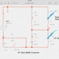
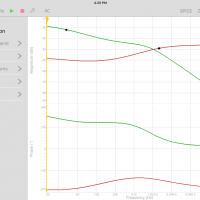
Since I personally like the sound and smooth transfer characteristics, an 1100 Hertz two-way shunt crossover was used. Crossovers of this type interact with the electrical characteristics of the speaker drivers so once these parameters are measured, the entire circuit can be modeled in SPICE to optimize the component values and performance. Multisim Touch, a National Instruments product, is available free for the iPad and was used for this purpose. In addition to the shunt crossover for the drivers, a series RL network was included to compensate the baffle losses that roll-off at 6dB per octave. The conjugate 6dB per octave reactance characteristics of the RL network will flatten the natural roll-off and thus flatten the frequency response of the entire system. When using RL networks of this type, some trial and error is unavoidable as is some loss in driver efficiency. A 10dB loss was deemed acceptable to have the necessary low frequency extension to make the Coley OB15 a full range speaker. Although the RL components are not available from Parts Express, they are easily available from sources like Mouser. The 50 ohm resistor used in the network is metal and highly recommended due to the higher heat dissipation capability.
Tips & Tricks:
There is nothing special about using a rack for these speakers, construction could have just as easily been all wood which would allow omitting the rack. As long as the approximate width and height are maintained, the performance will be nearly identical. For those concerned about maintaining a constant load over frequency, a 12 ohm load across the speaker terminals can be added with little or no change in performance; simply size the resistor wattage according to expected power. Like any open baffle, it is best to place the speakers at least three feet from the wall for best results.
Conclusion:
The performance of this speaker was beyond my initial expectations. For someone who is accustomed to the bass characteristics of a ported enclosure, the transparent and encompassing bass of an open baffle was a pleasant surprise. The sound from this open baffle speaker surrounds the listener and it is easy to imagine yourself in a smoky bar listening to a live jazz band.
About the Designer:
This project was designed and constructed by Craig J. Coley of Burleson, TX. I work as an electrical designer and am listed as inventor on 8 US patents in the field of electro-optics. I have been an electronics hobbyist since I built my first Heath radio at age 7 and a ham radio operator since age 11.
Parts Used:
Goldwood GW-215/40/8 15” Woofer, P/N 290-346
Beston RT002A Ribbon Tweeter, P/N 277-116
Dayton 40 uF, 250V Poly Capacitor, P/N 027-442
Jantzen 0.6mH Inductor, P/N 255-412
Triad C-56U 35.0mH Inductor
Vishay/Dale RH02550R00FC02, 50 Ohm, 25W Resistor
Tripp-Lite SR2POST12, 12U Desktop Rack

Looks like they would sound great. Great work!
Also, I’m in Burleson as well. I would definitely like to hear these, given the chance!
Daniel, my email is craigjcoley@gmail.com and I live about 2 blocks from Centennial HS
I like the design of this and am planning to make one of my own to see how I like it…
But I must admit I am very new to this, so I can merely replicate what you’ve done part for part.
My hangup right now is that I’m not sure how things are wired under the capacitor based on the image. I don’t know for sure how it’s all tied together and I just want to do what you did so I know it’s right.
Could I bother you for a closer picture of the wiring under/around the Capacitor?
and perhaps a closer picture of the wiring around the Triad Inductor so I can see how it’s all wired in?
Wiring is quite simple with the 600uH inductor connected in parallel with the tweeter, the 40uF capacitor connected in parallel with the woofer, and the 50 ohm resistor connected in parallel with the large 35mH inductor. Once this is done, the two speakers and the 35mH inductor/resistor are all connected in series with each other to the speaker terminals.
really like your idea but I think I will try a DML instead of a ribbon.
Nice project!
Simplicity above all.
Thanks for your information.
Regards.
A.
I couldn’t get any bass at all from these woofers. I bought two of the 4ohm versions and nothing. I used them in a totally open baffle. What am I doing wrong?
Frank – placement is the key. I have huge amounts of fast bass slam from these in H frames but moving them a foot or two makes a big difference. And there will be peaks and nodes in your room. You need to move them around and then find your best listening position. If you cant do that in your existing room then you need a box to get around that, but if you can, its far far better than boxes in terms of full range speed and accuracy and really worth it.
Placement – you and the speakers . But with some work it is really worth it. I have huge amounts of fast and slamming accurate bass in a 20Ft Wide room. But you will have peaks and nodes. Experiment get a DSP and its worth it
Hello
I have an Ampero guitar processor going into a peavey 50 50 power amp.
Do you think these would work well at low volumes as it’s a frfr speaker?
Alex
This project seems to be exactly what I’ve been looking for, and very well documented indeed, with excellent results for the costs involved. I am surprised at how few comments and inquiries this project has generated though, given the explosion in interest in open baffle designs. Have you (or any readers) done any further development, for example using different woofers or perhaps wide range AMT tweeters? I could spring for more capable drivers if the expense results in better performance (either measured or subjectively). I would love to read about any results along those lines before buying the parts listed and committing to the initial design. Thanks to all!
Hi Craig,
I noticed that the crossover frequency of your speaker is given as 1.1kHz, while the FR of the driver is 1kHz – 40kHz, and a suggested crossover of 2.8kHz by the manufacturer. Isn’t this conflicting? I do like the system and consider to make it, but the low crossover frequency seems an issue to me.