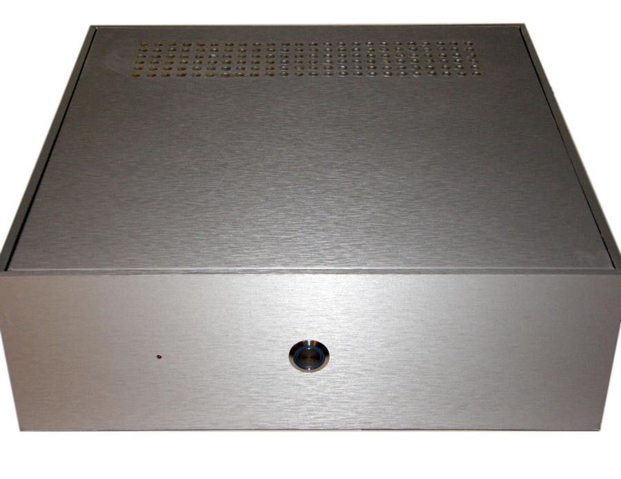
GOJIRA Solid State Power Amplifier
Designer: Hong Nguyen
Project Category
Amplifiers
Project Level
Advanced
Project Time
20+ Hours
Project Cost
$100 – $500
Project Description
This is a class AB, high output amplifier, capable of delivering 250W/channel into 8 ohms, or 350W/channel into 4 ohms, designed mainly around components that Parts Express carries. Components that I added to improve the quality of the amplifier are soft start, DC supply, speaker protection modules, and a temperature regulated circuit for the fan. This is an advanced project, and requires that you understand the dangers of AC as well as DC voltage. Having said that, if a person with no electronics background such as myself, can end up bringing this project to fruition, any of you speaker geeks can do the same and better.
Design Goals
The goal of building an amplifier, in my opinion, is to end up with something powerful that can accommodate music dynamics easily without clipping, while delivering low distortion and the absence of hum or buzz during quiet passages. The amplifier also has to be able to protect your valuable speakers should components fail, and electronic components do fail. Everyone who knows me knows how loud I listen to music, and since watts are cheap, why build a 25W amplifier when you can buy a 350W mono module for 35 bucks?
Driver Selection
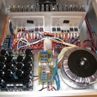
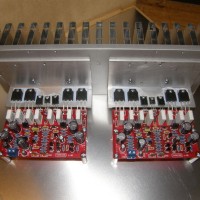
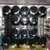
a. Amp Modules: I chose the Yuan-Jing mono amplifier modules for this project, for their attractive prices ($70 for the pair), and mated them with the Sure 35,000uF power supply module ($60) that PE has been carrying for a while. The YJ module is very similar to a less powerful amplifier module that I built in the past, and the wiring is comparably straight forward.
b. Power Supply: The Sure power supply has built-in dual rectifiers attached to heat sinks, and LED arrays that show the rectified voltage for each rail (negative and positive), and well as indicate when the capacitors are completely discharged in the event you have to disconnect or reconnect the amp modules. During testing, the Sure modules completely discharge within 15 seconds, allowing you to work on it practically right away.
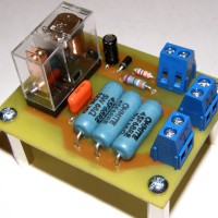
c. The soft start module was built from scratch from a Texas Instrument schematic. After doing point to point soldering for my first 3 amps, I decided to do a PCB for this project. For details on how to “PCB the easy way”, please look at one of my threads on the Tech Talk forum.
d. The DC supply is basically a simple circuit that takes an AC voltage (in this case a 18VAC secondary) and converts it into a DC voltage using a small full bridge rectifier, then regulates it into 12VDC using a LM7812. This circuit was also built from scratch and put on a PCB. This module powers the fan and the LED of the power button.
e. The speaker protection module is an eBay kit, the XY Speaker Protection module V.2 ($5.00). I have used this module reliably for the past 5 years, and it has worked protecting my speakers many times, when my DIY amp modules has blown up or failed. The module has a red LED that lights up briefly on power up, then goes off, and stays on if an amp failure is detected. For this project, I moved the LED to the front faceplate, next to the power button, so any failure can be instantly detected. This module requires 12VAC, and has an on board rectifier.
Enclosure Design
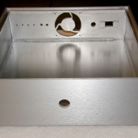
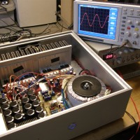
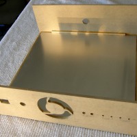
The case is constructed entirely of MDF, and is 16”W X 16”L X 5”D. The bottom is 1/2” thick, while the rest is 1/4” thick. The exterior is covered with the new PE metallic vinyl, and the interior painted with metallic paint. The opening for the fan was cut with a jig saw. The top was first covered in vinyl, then drilled to allow venting of the large heat sink.
Enclosure Assembly
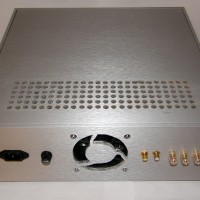
a. The bottom piece of the enclosure is lined with a sheet of aluminum (Home Depot item) and connected to earth ground. The following components can be found on the rear panel: IEC receptacle, fuse holder, 12VDC fan, RCA inputs and speaker binding posts. For the inputs, I used insulated microphone wire. All other wirings were done with 16AWG stranded copper wires.
b. The transformer is an Antek 6440, delivering 600VA, with 3 sets of secondaries: 40VAC, 18VAC, and 12VAC. Even though the amp modules only specify +/-45VDC, I have used higher voltage on another similar module reliably, thus my choice for the Antek, which delivers a rectified voltage of +/-56VDC. The 18VAC secondaries power the DC supply, and the 12VAC secondaries the speaker protection module.
c. The DC supply powers the fan and the power button LED. This circuit consists of a 2A full bridge rectifier, a LM7812 voltage regulator, and a couple of 0.47uF capacitors.
d. The schematic for the soft start can be found on TI’s application note AN-1849. The component cost for this module is about $8.00, and has served my amp builds very well for the past 5 years.
e. To ensure the proper heat dissipation, I added a temperature regulated DC fan. This circuit consists of 3 components that cost around $5.00, and can be found on www.heastsink-guide.com: a MOSFET power transistor, a 10K trim potentiometer, and a 10K NTC temperature sensor. This keeps the fan idle on startup, and keeps the overall noise down even when the amp warms up.
f. As described above, the speaker protection module, powered by the 12VAC secondaries, is quite reliable for something that can be had for $5.00 on eBay.
Conclusion
The build was easy, straight forward, and drama-free. The sound is superb at normal listening volume, but I can’t wait to take it through some more serious testing later. This amp sounds very similar to my Rod Elliott’s Project 101 that I did almost 2 years ago, and for $35.00 per module, you can’t really go wrong there. However, it wouldn’t be fair not to mention some cons as well:
a. Complete lack of instructions, so unless you’ve built amps before, you have to be able to figure out where the connections go (no instructions came with the Sure power supply either).
b. The right channel is slightly warmer than the left channel, and in the absence of a bias adjustment component, there’s no way to adjust their “idle” speed.
Overall, this amp delivers great sound, great value, and a high level of satisfaction due the fact that it requires quite a bit of DIY skills. As you can see, all I did here is to pull knowledge from the internet and put it together in a package that complements components offered by PE, and not for a whole lot of money either.
About the Designer
Hong Nguyen is by day a Director of Operations for a healthcare company that develops and manages ambulatory surgery centers. He has been building speakers and amplifiers for almost 8 years, and is a member of the Speaker Building Design Team.
Project Parts List
|
Part # |
Description |
Qty |
|
320-6520 |
Yuan-Jing Mono Audio Amplifier Board |
2 |
|
320-3372 |
Sure 100V 30A 35,000uF Rectifier Board |
1 |
|
NTE303 |
Silicone Thermal Heat Sink Compound |
1 |
|
060-708 |
SPST Rocker Switch |
1 |
|
070-610 |
Fuseholder |
1 |
|
320-470 |
Perforated PC Board |
2 |
|
250-014 |
AC Cooling Fan |
1 |
|
350-539 |
Steel Aluminum Vinyl Wrap |
1 |
|
090-442 |
Power Jack Chassis Mount |
1 |
|
320-3375 |
Binding Posts |
1 |

This is an excellent build. Very nicely done Hong.
If you had not mentioned in the article that the case was MDF and covered with Metallic Vinyl and metallic paint, I would have thought for all the world that it was machined from nice sized chunks of aluminum. You did a convincing job of making it look like machined aluminum. Nice job!
Great project. Amazing work on MDF for enclosure. I would like to enjoy DIY an amp to drive a passive subwoofer; but as usual the experts around the world discourage! I would like to give it a shot relying on this project by you and see how it goes.
Could add details of:
The soft start module – circuit diagram & parts list?
The DC supply full bridge rectifier – circuit diagram & parts list?
The speaker protection module – a link? or may be a picture showing the components?
I wish you had more hobby kits inside the book
Great looking little project. Would it be possible to make this as a 3 channel amp? I am wanting to give my LCR a bit of a boost and it seems that there are not many 3 channel amps on the market.
Very nice build. I also read the article in the Parts Express flyer. Where did you get the awsome power switch? , and where did you get the massive heatsink?. Thanks.
What output transistors did you use, exactly?
Please email me at hongrn AT sbcglobal DOT net for more info. Thanks.
Great Amplifier and craftsmanship! Is there a way to make a 5 or 6 channel version?
Awesome build. Clean and powerful.
In future, it would be better if you list ALL components used, such as the power transformer and the soft start board, in the parts list.
I’m even more impressed by your ability to put these components all together with little documentation. Many times I’ve found technical info online just by googling the part numbers.
At least most of these boards have the connections silk screened onto the PCBs.