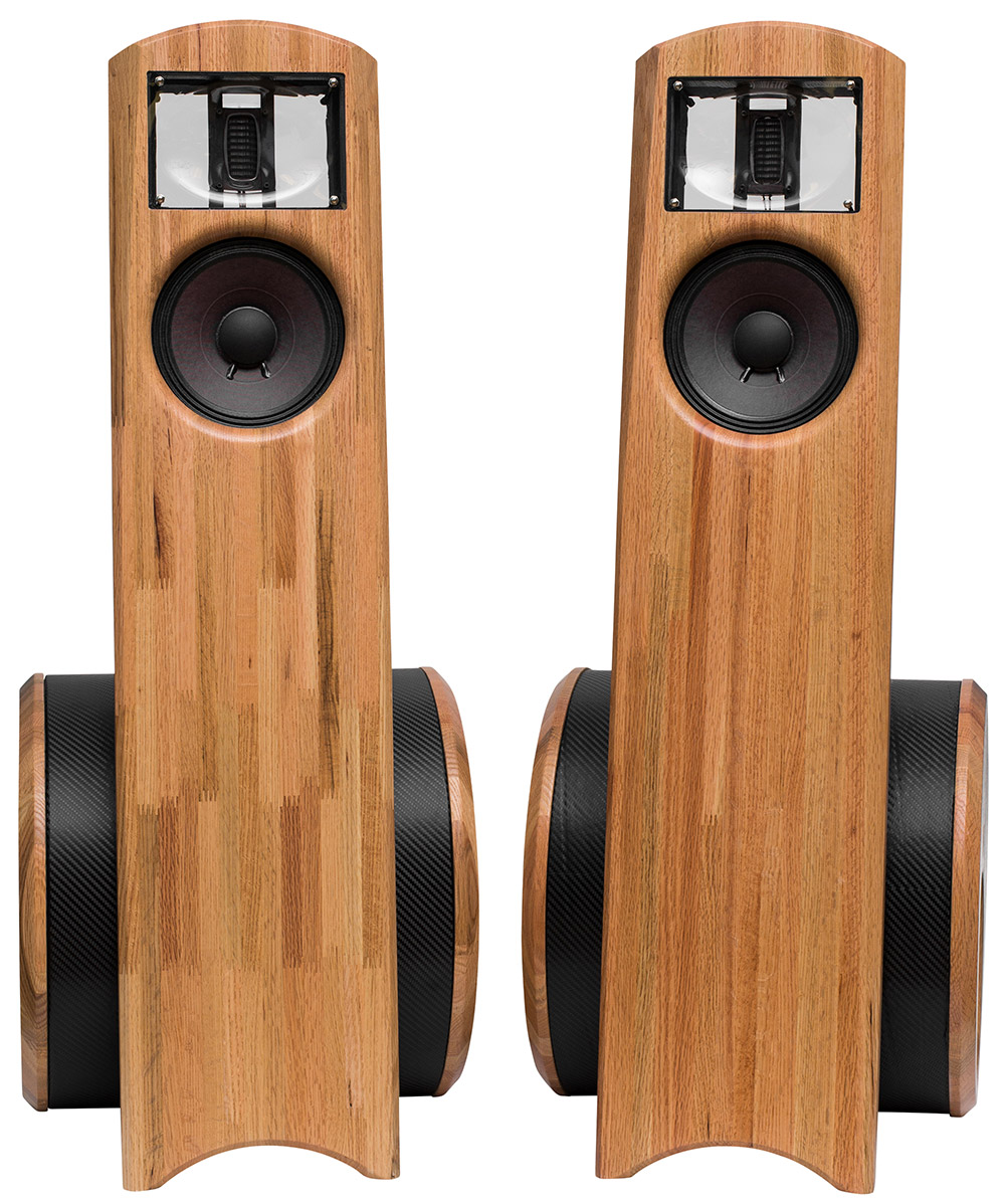
The Segue’s
Segues Crossover layout – final published.pdf
Designer: Dan Neubecker
Project Description
The Segue name symbolizes this design in that the design segues between sealed and open baffle design approaches as well as between traditional hi-fi drivers and a pro midrange. The title of this project is a play on the Segway, which it resembles in form, and the musical word segue, which means to move without interruption from one song, melody, or scene to another.
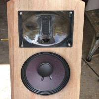
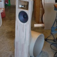
The Segue’s are a full range, passive 3-way utilizing 4 drivers per speaker. The bass frequencies are covered by dual, opposing, push-push hi-fi woofers in a sealed tube. The midrange is an 8” professional driver in an open baffle, dipole configuration. The tweeter, also implemented open baffle, dipole, is an AMT type configured with front and rear waveguides.
All drivers are currently available for purchase at PE.
Design Goals
1. Full Range, floor standing 3-way speakers that remain reasonably sized and less unobtrusive than most speakers with these capabilities
2. Relatively high sensitivity
3. No baffle step application for the woofers
4. Elite performance and aesthetics for a very reasonable cost
5. Directivity matching between drivers for flat power response
6. Capability for distortion free, high spl levels and dynamics
7. Acoustically dead cabinets and baffles
8. Outstanding but unique aesthetics, presenting as pieces of art or sculpture
Driver Selection
Woofers: The Dual woofers are RS225-8’s in parallel. Mounted as close to the floor and nearer the front wall boundary than the midrange and tweeter, these need little to no baffle step compensation and hence there is no loss in overall system sensitivity.
Midrange: A single Eminence Beta 8A mounted from the rear and implemented open baffle, dipole.
Tweeter: A single, waveguide enhanced, Aurum Cantus AST2560 amt-type tweeter, implemented open baffle dipole.
Enclosure Design & Assembly
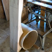
The woofer enclosure is made from 15” interior diameter, ½” thick cardboard tubes, about 42 liters in volume. The baffles 1-3/8” thick, red oak laminated and recessed baffles are held in place by a single threaded rod that pulls the baffles together, yet allow them to be removed in order to disassemble the entire speaker or replace drivers. The bass bin is bolted to the main front baffle through the use of two ¾” plywood cradles that sandwiches between the tube and the front baffle, held in place by three bolts installed inside the tube so they are not visible. The wood cradles are painted with truck bed liner. The woofer bass bin is covered with carbon fiber vinyl for a contemporary look and in accordance with the black and wood theme.
There is no midrange or tweeter enclosure in this case. The midrange, however is not bolted directly to the front baffle, but instead is pressed into place by the same plywood cradles that hold the front baffle to the bass bin.
The tweeter face plate has been removed and mounted on narrow aluminum rails so that it’s visual footprint is reduced, seemingly floating within the clear front and rear firing waveguides. The waveguides are sandwiched in place on each side of the rail mounted tweeter, held in place with through bolts that have been painted flat black to reduce their visual impact.
The entire enclosure can be disassembled. Also of note is the combination of sloped back baffle, with rear mounted mid and waveguide mounted tweeter to be acoustically aligned the same distance from the listener’s ear, offering potential flexibility in crossover design as well as improved aesthetics. The front baffle is chamfered along the tweeter to further reduce any edge diffraction signature that the waveguide does not address.
Crossover Design
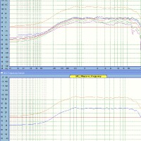
This one has a fairly complex crossover, with 20 parts. Two notch filters were used, one each in the midrange and tweeter stop bands to shape the knee and provide as flat a response as possible. The woofer to midrange crossover is and Linkwitz Reilly 4th order (LR4) with the crossover point at about 275 Hz. The midrange to tweeter is LR2, with a crossover point of 1850 Hz. Attached are unsmoothed plots of the speaker response measured at 0º, 15º (the design axis), 30º and 45º, and above that will be the summed response of all 4 measurements. Below this is a graph with just the summed response and the design axis response for comparison. You will see that the response balance is very much the same at all axis points, which points to an excellent directivity match and that the summed response also matches the design axis response very well.
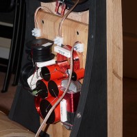
The crossover is mounted in a unique way to the same laminated oak, but inside the vertical rails on the back of the speaker. Since it was to be visible, I went to extra effort to make it attractive and unique, by counterboring holes for many of the parts and mounting them vertically. I purposely used Audyn caps for the attractive black and red that fit well with the overall project theme in addition to there excellent construction, sound and value. I have included a photo of the finished crossover. Wiring is very well hidden.
Conclusion
This was a fun and relatively easy project to construct. It is one of my favorites for both aesthetics and sound quality. For a 3-way with three 8″ drivers and 1-3/8″ thick baffles, it is quite light and relatively easy to move around.
About the Designer
Dan is a member of the Parts Express Speaker Building Design Team.

Good lord!!! Incredible talent!!! Beautiful. That crossover is really complex looking!!!
I don’t understand the value of posting these projects as being helpful in anyway to Parts Express customers or to Parts Express in their sales effort if the presenter does not submit the design plan along with the crossover schematic like everyone use to. Otherwise Parts Express should call this, “Parts Express Picture Gallery.”
We appreciate your honest commentary and are working with project owners to provide as much in-depth information as possible. Since our project gallery involves submissions from other customers, not all projects include the details some may want in order to replicate. Our project gallery is intended to be inspirational as well as informative, and you will find a mix of details from project to project. Ultimately, we want our customers to feel free to share their ideas with others and we hope you can still find inspiration in some of the ideas.
I heartily agree with Douglas Jacobs. SHOW THE CROSSOVER SCHEMATICS ON ALL PROJECTS !!!
Please see response above 🙂
Looks good! Is the waveguide for the AST2560 available form somewhere?