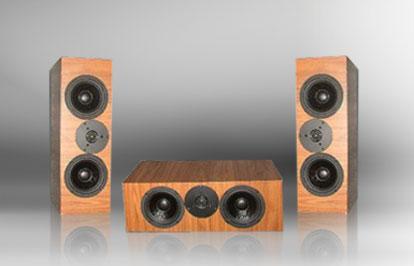
Triune


Designer: Curt C.
Project Time: 8-20 hours
Project Complexity: Professional
Project Cost: $500-$1000
Driver Selection
The MTM configuration, while its vertical off-axis response is perfectly acceptable in a vertical alignment of drivers, generally exhibits unacceptably poor horizontal off-axis response when orientated with the drivers aligned horizontally. This may be due to the philosophies of the designer, or constraints of the drivers and crossover topologies utilized. In other words, if the MTM was not optimized for horizontal orientation, it likely will exhibit audible combing effects off-axis. The scope of this design exercise was to determine if good horizontal off-axis response could be attained using the chosen drivers, and what crossover topologies were more acceptable to this endeavor.
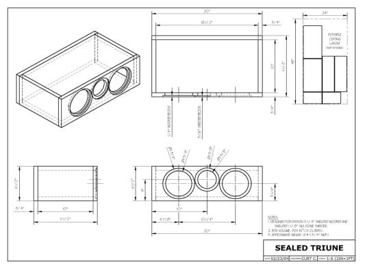
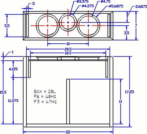
Enclosure Design
Below you will find drawings for several possible enclosures for this design. The first picture is the original sealed design– I am indebted to Sandy H for providing the drawing and building the sealed enclosure for me. The second is a vented design submitted by Eric Y, and is for those who want the added low end extension a vented design offers. The slot ports only slightly add to the baffle width and calculated to provide an f3 of 47 Hz. vs. 90 Hz for the sealed design. The deep enclosure would be ideal for undermonitor placement, but could be used above the monitor as well.
Amplifier/Crossover Configuration
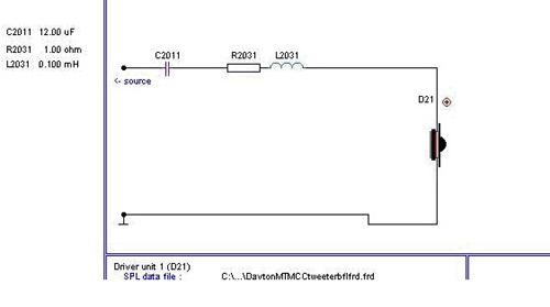
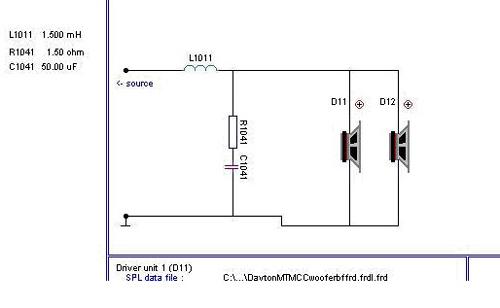
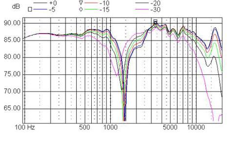
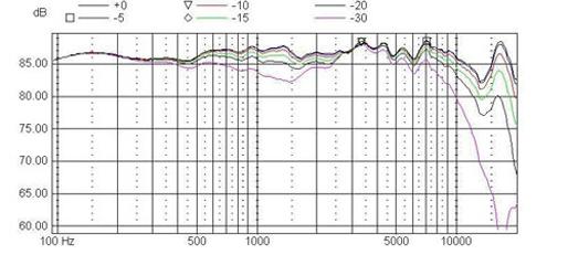
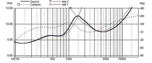
A little Theory: The maximum crossover point in most speaker designs is generally that frequency whose wavelength is equal to the center-to-center spacing of the adjacent drivers, that is woofer to mid, mid to tweeter, etc. This is an appropriate rule of thumb for speakers with vertically aligned drivers as the vertical listening angle varies very little from seated to standing. With horizontally aligned drivers however, we must contend with a much larger off-axis angle, and consequently for a horizontal MTM design, I suggest we must be concerned with the maximum center-to-center spacing of the two woofers, and use that criteria as the acceptable minimum crossover frequency. The quandary is that the woofers need a lower crossover frequency than most tweeters are capable of, to produce a good off-axis response. A little more Theory: I modeled many different crossover topologies during this study. I found the best results for my criteria were with lower order underlapped designs, but like most designs, the actual driver responses, especially the woofer, determined the actual crossover used. A crossover network using Butterworth filters will sum + 3 dB when both low-pass and hi-pass filters are at the same frequency. However if the woofer crossover point is moved down in frequency, it is possible to obtain a reasonably flat response, with only minimal peaking. Setting the tweeter filter network to model a 2nd order Butterworth acoustic target response at 1900 Hz, I was able to move the woofer crossover point down to 1200 Hz, and approximate a 3rd order Butterworth acoustic response. This lower low-pass filter frequency allowed significantly more spacing between the woofers with acceptable horizontal off-axis response. The crossover topology: I’m a firm believer in the KISS principal in crossover design. That and the budget nature of this design resulted in a very simple crossover network utilizing only 6 components. The woofer net is a series inductor and shunt cap with the Q limited by a resistor. This results in an electrical filter gain of -8 dB / octave, and when summed with the driver response, provides an average acoustic response of approximately 3rd order BW. The tweeter uses a series cap to derive the 2nd order BW acoustic response, and a series inductor to slightly roll off the extreme high end at -2 dB / octave. Parts notes:As ususal, any resistor with a value of less than an ohm is the DCR of the assocaiated inductor and should be ignored. R2031 shows the value (1 ohm) plus the DCR of L2031.All caps and resistors are specified as Parts Express parts, but certainly you can substitute your favorite brand. The inductors specified are Jantzen 18 gauge air core. Comments on Measurements: The results of this final design are very encouraging. As you can see from the frequency response plot, the on-axis response is reasonably flat with approximately 4 dB of baffle step compensation. The modeled sensitivity is roughly 87 dB. When used as a center channel, the horizontal off-axis plots indicate a maximum deviation of around -5 dB at 30 degrees off-axis. While this is not ideal, it is quite acceptable compared to the other topologies I investigated. The off-axis plot with the tweeter reversed shows good phase tracking through the crossover region, even off axis, something I was unable to attain with my preliminary designs. The vertical off-axis plots show very little variation even 60 degrees off axis, indicating very acceptable performance when used vertically as a left or right main speaker. The impedance plot has a minima of 4 ohms, but is above 6 ohms for a significant portion of the drivers passband. While I’ll call this a 4 ohm impedance, I suspect many commercial designers would consider this a 6 ohm speaker.
Project Parts List
|
Part # |
Description |
Qty |
|
295-301 |
1 |
|
|
275-075 |
1 |
|
|
027-430 |
1 |
|
|
004-1 |
Dayton Audio DNR-1.0 1 Ohm 10W Precision Audio Grade Resisto |
1 |
|
255-202 |
1 |
|
|
255-260 |
1 |
|
|
004-1.5 |
Dayton Audio DNR-1.5 1.5 Ohm 10W Precision Audio Grade Resis |
1 |
|
027-354 |
1 |
Hi, Sorry for stupid question but why in High pass filter an inductor is in series with tweeter?