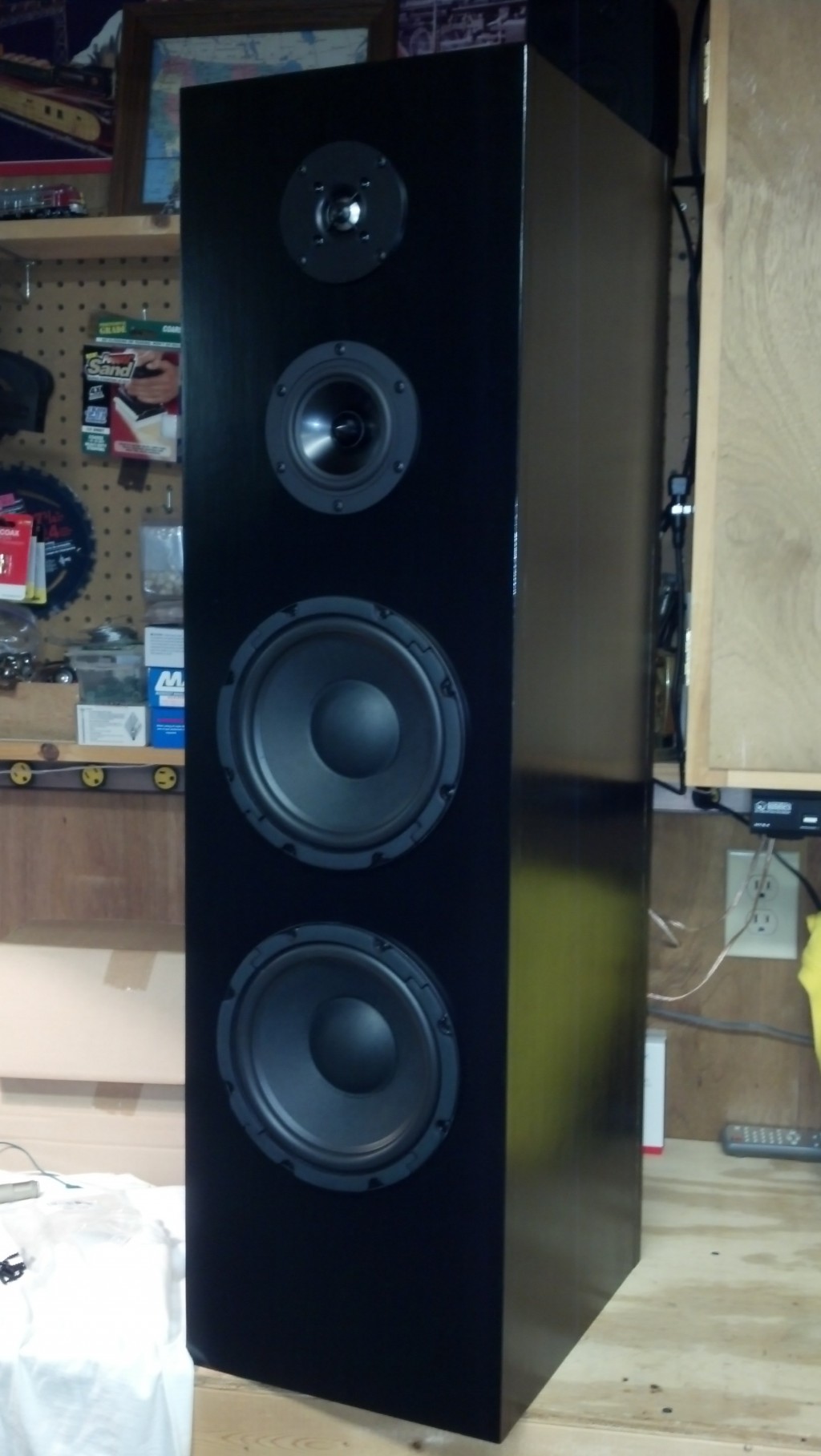
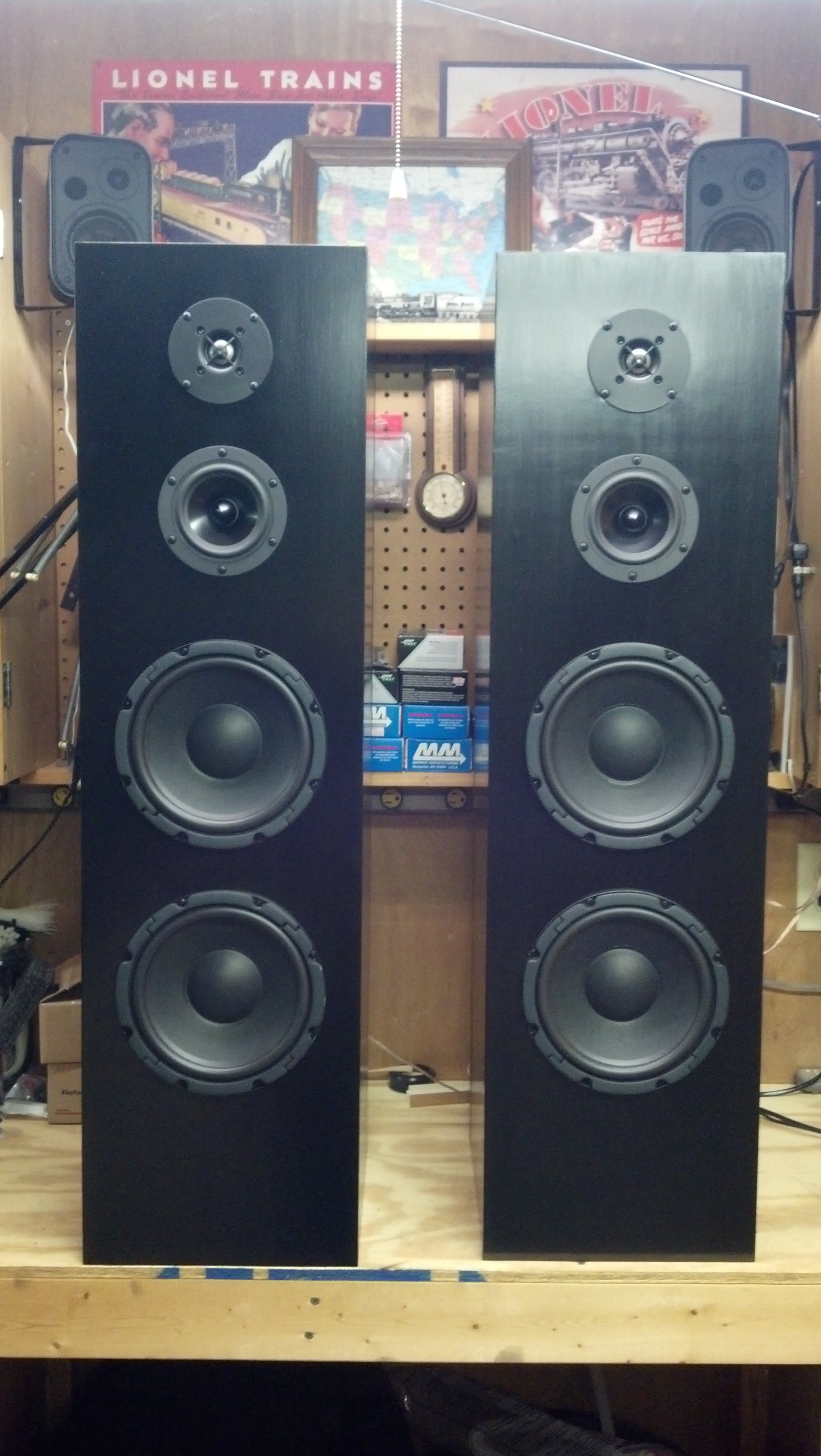
4 Driver, 3-Way Floor Standing Tower Speaker


Designer: Mike P
Project Time: 8-20 Hours
Project Complexity: Beginner
Project Cost: $100-$500
Project Description
4 driver, 3-way floor standing tower speaker
Design Goals
The goal of this project was to build a pair of speakers that would produce sub woofer-like bass for use with my vintage 1978 integrated amplifier.
Driver Selection
• Dayton Audio DC25T-8 1″ Titanium Dome Tweeter Part # 275-045 – 8 ohm, frequency response 3000Hz to 20,000Hz, sensitivity 93dB
• Dayton Audio RS125-8 5″ Reference Woofer Part # 295-353 – 8 ohm mid-woofer w/aluminum cone, sensitivity 87dB, frequency response 65Hz to 5400Hz
• Closeout model 930064 8″ Heavy Duty Woofer with Rubber Surround Part # 299-363 – 4 ohm, 80 watts each, frequency response 35Hz to 1500Hz, extended frame for greater linear excursion
Enclosure Design
• ¾” five ply cherry vinear plywood left over from a previous project.
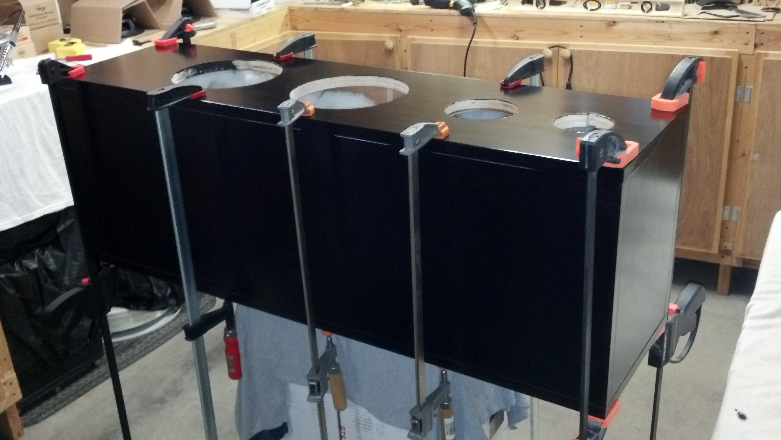
• Cabinet size OD of 40”H x 11”W x 14”D.
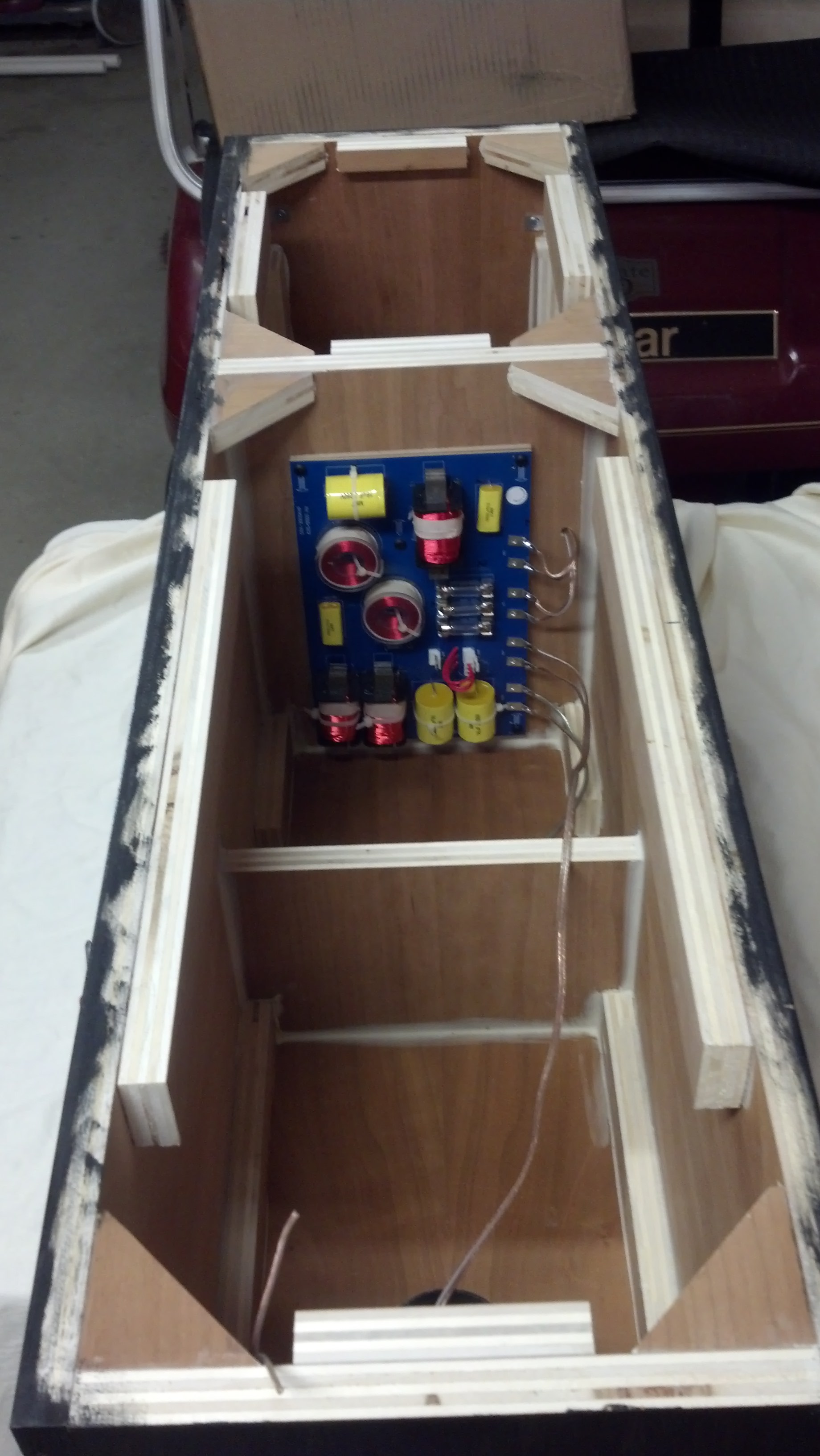
• Heavily braced interior cabinet
• Midrange and tweeter are isolated from the woofers
• Woofer area volume (minus all bracing) ~1.58 cu ft.
• High density polyfill acoustic dampening material
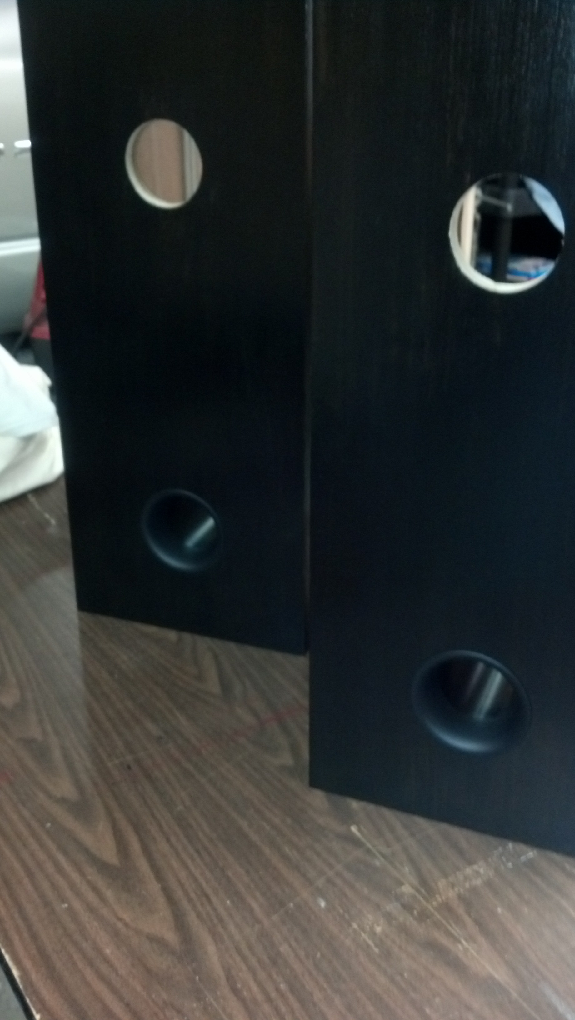
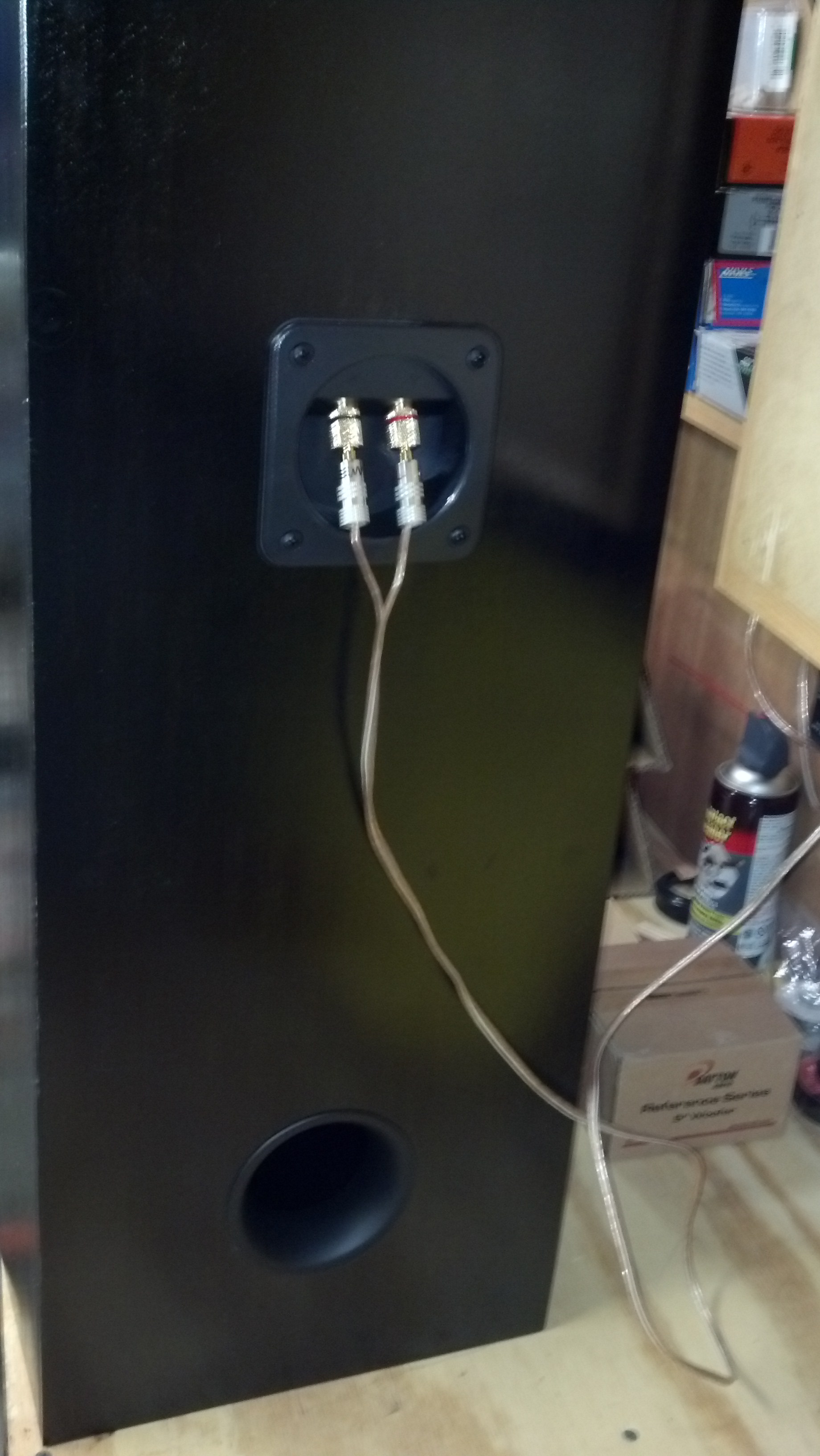
• Rear mounted flared port tuned to ~38hz (2½”ID x 8½”L cut to 4½” L , Part # 260-478)
• Gold plated banana binding posts (Square Speaker Terminal Cup 4″, Part # 260-284)
• Pre-built crossover – 625Hz and 5000Hz
• All connections to binding posts, crossover and drivers are soldered
Enclosure Assembly
Construction – For several years I’ve had some ¾” five ply cherry vinear plywood left over from a previous shelving project. The price was right and the pieces were already partially cut making them easier for me to handle than a full 4’ x 8’ sheet. I choose a cabinet size of 40”H x 11”W x 14”D. I began by cutting the pieces to the approximate sizes using the radial arm saw. Then I finished them on the table saw.
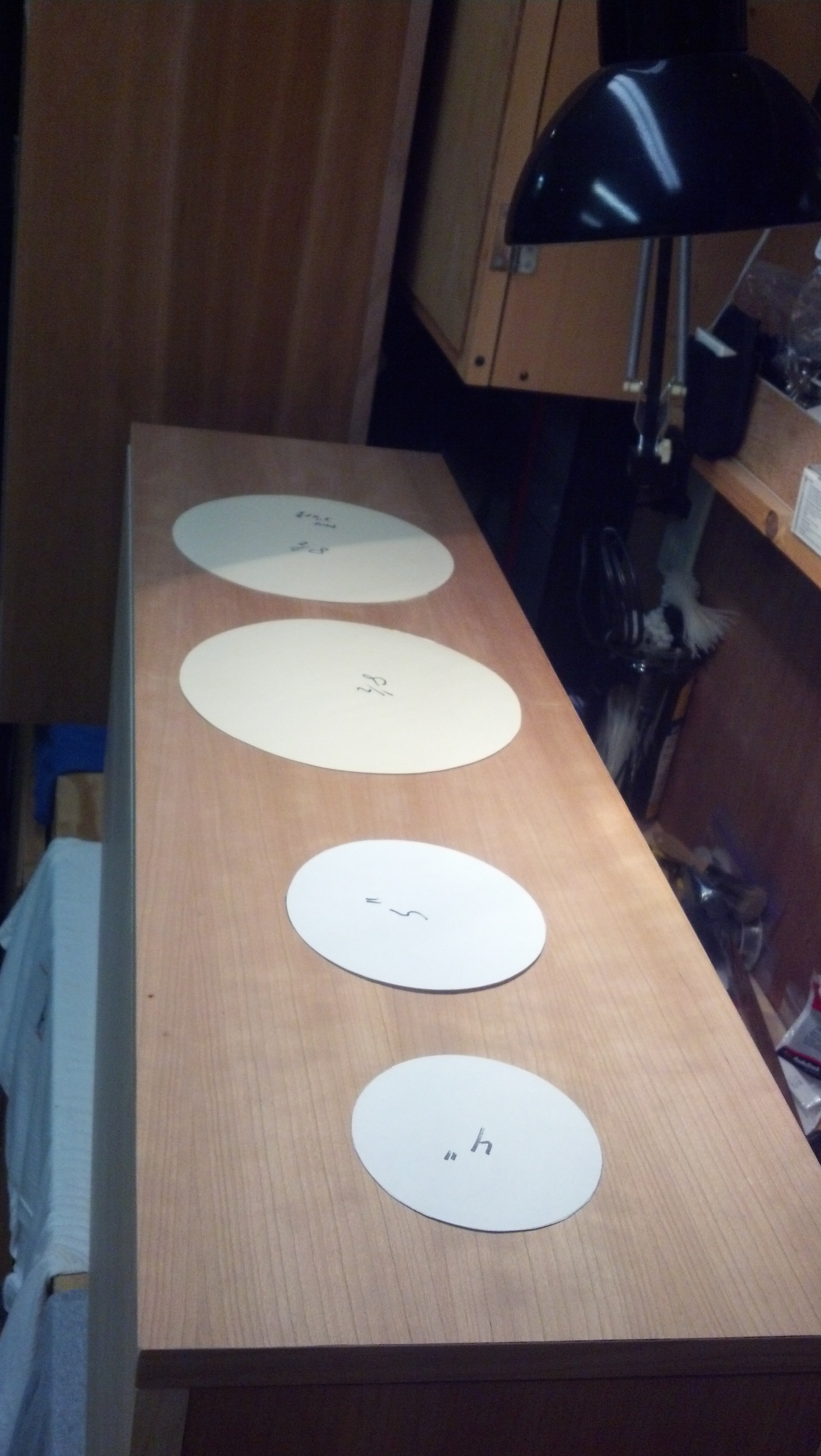
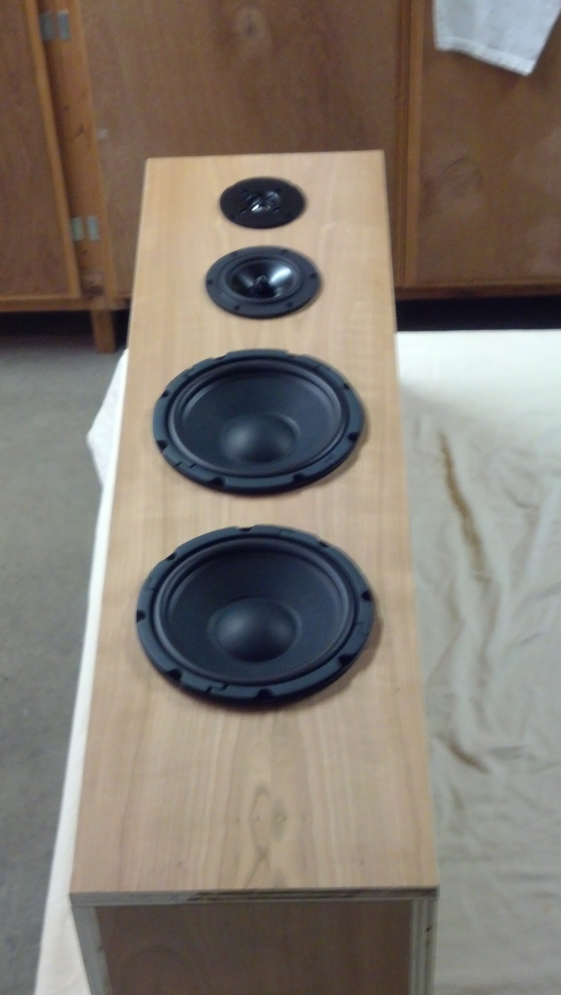
I purchased some metal corner brackets and installed 4 of them in the back corners of each of the cabinets to help hold the units together and square while I continued to assemble them. Using Liquid Nails, I glued battens to all the inner seems to hold, seal and increase the cabinet strength. I cut and installed a shelf creating a sealed upper compartment for the mid and tweeter speakers. I located the shelf about 1/3rd the length of the cabinet. The volume of this compartment is such that it does not need to be ported for the midrange. A large brace was added in the woofer compartment connecting the cabinet side walls to further reduce vibrations. I also cut small triangular pieces and glued them in all of the front facing corners where the front baffle would be attached. This provided additional strength to the enclosure and more surface area for gluing the front baffle. Next, I determine the layout of the drivers on the front baffle. I made thin card board templates for each speaker based on the size of each driver. The actual cutouts were smaller and these dimensions can be found on the specification drawings from the driver manufacturer. Three and four inch hole saws were used on a drill press for cutting the midrange and tweeter driver holes. A jigsaw was used to cut the woofer holes which were 7 1/8” diameter.
Crossover and wiring terminal location – I determined the best location to mount the crossover would be under the internal shelf that isolates the midrange and tweeter from the woofers. Removing the upper woofer would provide access to it if necessary in the future. The placement of the crossover, lead to locating the wiring terminal near the center of the rear panel. This worked out well since the only place to mount the port tube was likely going to be on the backside near the bottom of the enclosure.
Tuning Port location – I decided to locate the port on the back of the cabinet. Matt at PE calculated the port size. I provided him with the woofer cabinet volume and the part number of the woofers. Using Bass Box Pro and the woofer specs, Matt determined a 2.5” x 4.5” flared port would provide a tuning frequency of 38 hertz.
Wood finish – I wanted the cabinets to be black but the wood grain to remain visible, so I didn’t want to use paint. So, after much consideration, I chose Minwax Polyshades black satin. This worked pretty well. One coat was used on the cabinets and 2 coats on the front baffles. A clear coat of Minwax polyurethane sealer was applied a few days later.
Polyfill acoustic dampening material – The polyfill was stapled to the inside walls of the cabinet and to the back of the driver baffle.
Crossover and driver installation and wiring – Standard 16 gauge speaker wire was soldered to each of the driver connections on the crossover. A small hole was drilled for routing the midrange and tweeter wires to the upper compartment. Each driver connection was soldered to ensure no lose connections later on. Prior to mounting the drivers, speaker gasket tape was applied to the woofers to make an airtight seal. Gasket tape was pre-applied to the midrange and tweeters from the factory. The drivers were then carefully positioned on each of the front baffles and pilot holes drilled for the screws. A hand screw driver was used to install the screws. More control of screw pressure is achieved by hand tightening vs using an electric drill. One slip with a drill driver and a woofer or the finish on the baffle can be ruined.
Final assembly – Liquid Nails was used for gluing the baffles, side walls, back wall and all other support pieces. Ten large clamps were used to hold the units while the glue hardened.
Crossover Design
Prices on pre-built crossovers range considerably as well as the quality of the components that go in to building them. I wanted high quality components, such as metalized polypropylene capacitors in the upper frequency ranges and good quality inductors. I considered building my own but with being my first scratch build, I decided to purchase a pre-built crossover.
After extensive searching, I purchased from eBay a pair of pre-built crossovers with cutoff points of ~625Hz and ~5000Hz. These crossovers use high quality components. They have 8 ohm mid and tweeter impedance and switchable 4 or 8 ohm woofer impedance. This option allows for series wiring of a pair of 4 ohm woofers or parallel wiring for a pair of 8 ohm woofers. The crossovers have individual speaker fuse protection as well as top of the line inductor coils and metal film capacitors specifically designed for audio use. Standard 16 gauge speaker wire was soldered from the crossover to each of the driver connections.
• 3-way, 2nd order (12dB) reverse polarity
• 625 Hz/ 5000 Hz
• 8 ohm tweeter/8 ohm midrange/8 ohm woofer (w/option for 4 ohm capability)
• band pass gain ~ 2.5 dB
• spread ~3 octaves
• all precision metalized film capacitors in the midrange, tweeter and low pass signal paths
• utilizes both air and iron core copper wound inductors
• all driver paths are individually fused
Conclusion
I was very happy with the final product. Being my first build, I feel I could improve on the cabinet construction appearance which I will on my next pair of towers. However, I feel I met my goal of building a speaker with sub woofer-like bass when used with my vintage integrated amplifier. The sound quality and bass produced greatly exceeded my expectations. On the construction end, the enclosures are very solid. The black finish matches my other home theater components. Currently the speakers are connected to to a Russound two input, 6 speaker out speaker switch so I can run them through the vintage amp and my AV receiver.
About the Designer
Since my teenage years, I have been interested in electronics, specifically stereo equipment, speakers, amps, etc. I still use my 1978 integrated amplifier as my primary audio source for playing CDs and vinyl. I like the simplicity of the vintage equipment along with the build quality, real aluminum knobs, aluminum face plates, the feel of quality. The pursuit of better quality is what drove me to try building a set of speakers. Thank you Parts Express for your support in this hobby.
Project Parts List
|
Part # |
Description |
Qty |
|
275-045 |
2 |
|
|
295-353 |
2 |
|
|
299-363 |
2 |
Can you please post a link to the crossover you used! I would like to build them!
Thank you!
Thanks for your interest. I am very pleased with these crossovers so far. ebay item number 331261764738 Thanks again.
How did you design the dimensions of the cabinet and tune the port to the drivers?
Looks Great btw!!
Cheers,
Hi Christopher. I chose the outside dimensions based on two things: one was the available space where I was going to place the speakers when finished (next to my TV and other AV equipment) and two, I researched and reviewed the dimensions of many 3-way tower speaker models on the web and tried to get a general feel for the average sizes. So I chose 40″ x 11″ x 14″ which would fit in the available space I had. For tuning the port to the woofers, you must calculate the interior area where the woofers are located by measuring the l x w x h in square inches minus the area of any battens or other support structures. Once I had this number, I asked the Parts Express team to calculate the tuning port length and diameter and to recommend the port I should purchase. They also need the part number of each woofer since the speaker’s electrical characteristics are included in the calculation. I didn’t have the program to make these calculations. The Parts Express team was very helpful. Thanks for your question and please check out my latest tower speakers which I have posted in the project gallery, The Maverics. Thanks again.
Mike
How did you wire the woofers to the crossover?? Do you have a diagram for that??
Bob: The woofers are both 4 ohm and are wired in series. A wiring diagram as well as many more build photos can be found at my website http://www.mrgigawatt.com. When you get to the site, follow the link for DIY. I hope this helps. Thanks for your interest in this project.
How tall does the fully built product stand?
40 inches tall, 11 inches wide and 14 inches deep
Hi Mike,
I need to import two tower speaker cabinets to fit in the following speakers.
Dual 8″ Woofers, 5″ Midrange and 1″ Aluminum Tweeter
whom do I contact with regard to ordering these.
The above are from my Yamaha NS 777 speaker cabinets which are bow in bad condition.
Your advise would be much appreciated.
Thank you
Earl
The original woofers aren’t in stock anymore, what woofers should i use instead?
Hi Mike;
First, I would like to say thank you for such a well written, well documented “how-to” outline of your project.
The speakers look fantastic and I can only imagine their sound.
Second, I’m having trouble accessing your website regarding the wiring diagram. I would really like to see how the wiring was connected from the crossovers to the individual drivers prior to soldering. Thanks again.
Hi Mike. First of all congratulations for your excellent job.
Here goes my question: Would it be possible to add a second mid-range woofer with what crossover? Connecting them in series (4 ohm) or in parallel (8 ohm)?
If possible, how would it affect to the power requirements of the amplifier?
Thanks so much!
Hi Yago. Thanks for your interest in my speakers. To answer your question, I believe you can purchase the Dayton Audio RS-125 in the 4 ohm version, part number 295-370. You could connect 2 of these in series and use the same crossover. Should work fine. Im not sure about the change in the power requirements but I would expect no issues adding an additional midwoofer. Thanks and good luck with your project.
Thanks so much!
I saw the Mmvericks, that’s why I wanted to add another mid driver. It looks nicer with 5. My idea is build kind of a mix of both but with a more “striking” but subtle design (maybe lining it with denim cloth and leather or even corduroy). Also, how would adding that speaker affect to the overall sound? Maybe louder?
The mid-woofer in the Mavericks is no louder than the mid-range and tweeter. It is not overpowering the sound of the other speakers. I may be wrong, but this could be due to the SPL of these speakers are similar.
Please also check out my other build, the Mavericks in the PE project gallery.
The worst aspect of this project is probably the off-the-shelf XO, which does nothing to attenuate a tweeter that is likely +7dB too hot (for the rest of the system), and the fact that it does nothing to suppress the metal-coned mid that “rings” terribly near 7.5k and again near 11.5kHz. Those peaks are probably at least as loud as the rest of the system, adding to the screamin’ tweeter in the top octave, and probably creating some real phase issues, possibly around 7kHz. Guessin’ that the actual XO pts. are really closer to 850 and 4k (which would not be that bad if that was the main issue). The “P” vers. of this mid MIGHT not have the resonance issues as badly as the Al cone.
CJ…Did you build these and have these problems or is this theoretical?
Did not build these, but not just “theory” … it’s science.
Most guys on PETT simulate XOs in software.
A 2nd order low-pass on this mid (w/out a “notch” near 7-8kHz) doesn’t effectively roll the mid off until about 10k. Along w/the unattenuated tweeter gives a response that rises around +6dB from near 4k up to 7-10k. OUCH ! (Also, the distance between the tweeter and mid should be minimized.)
Shouldn’t the parts list include either 4 woofers or just one tweeter/mid?
Is there a good second choice tor the no longer available “930064 8″ Heavy Duty Woofer with Rubber Surround 4 Ohm”? These look like what I’m wanting to build but I need help in picking drivers.
Thanks cj for riping my first speaker build. I know they are not perfect and wouldn’t stand up to a fancy name brand speaker costing several hundred dollars. But, I enjoyed building them and I learned a lot doing so. And, I think they sound pretty good. Not bad for spare wood lying around in my garage and some closeout speakers. Hopefully I inspired others to build their own as well. From all the comments I have received, I think I may have. Thanks for your input and good luck to you.
BEAUTIFUL WORK MATE, I UNDERSTAND FULLY ABOUT VINTAGE EQUIPTMENT, I HAVE AN SAE 2100L PRE-AMP IN THE SHOP FOR REPAIR. YOUR ENCLOSURES LOOK AWESOME, LIKE THE DETAIL OF CONSTRUCTION, REALLY SOLID, YOU MUST BE A CABINET MAKER , NICE WORK….ENJOY!!
cj…and exactly what is your expertise on speaker placement? Because it sounds like you don’t have a clue…are you
referencing line arrays, in which this clearly isn’t,…maybe the tweeter and the mid-range were focused to a specific
point basically nulling your “observation” of speaker placement on the same plane which for the sake of argument
really doesn’t matter in a home environment.
And for Mike…Congratulations on your first build, and I’m willing to bet they sound great!
(Don’t pay any attention to that “man” behind the curtain)
Thanks Randy for your kind comments. For my purposes, they sound great. I use them in my man cave. I upped my game on my second build, the Mavericks. Please check them out. Besides, this is supposed to be a fun hobby. Thanks again for your support.
Randy, I stand behind my 2 “perfect” posts 100%.
I ran box/XO sims based on this design and my goal here is only to try to steer future DIY’ers away from a design like this, when for the same money they could build a really great design (from over on PE Tech Talk). A good book for you to read is “SpeakerBuilding 201”.
BTW, I’ve been here for over 20 yrs and have probably built about 2 projects a year (using proper software tools and many times even using my own .frd/.zma measurements). I’m not unique in this regard. Projects here in the “Showcase” are not really “vetted” in any way.
If Mike likes listening to these, then that’s really all that matters.
The crossovers that he used are made by Audiopipe and can be found at ZXPC dot com
Question: how did you determine driver spacing? Particularly between the tweet & mid? I’m mostly concerned w/imaging.
This project caught my eye as I have considered a very similar project. I have the near-same collection of drivers w/a spare set of tweeters at my disposal in two pairs of speaker cabinets going unused. The irony is I may buy another set of tweeters as I’m not crazy about one pair’s SQ & the other pair is over 40 years old.
Thanks for the inspiration. Tony
can you replace the bass woofer with a car woofer .. in the same range.. car woffer.. -Skar svr-8 D4..4ohm/800watt max.
I have a question. For the. Woofers. Can. We use a car. Sub woofer.. like. Skar.8″.4ohm. Instead of the woofer that’s. On this. Plan. ?…..would that work…
I (personally) can’t even find “Thiele/Small Parameters” on those Skar subs – so … I’d certainly leave them on the shelf (UNless you’ve got your own WooferTester/DATS and can measure the T/S parms yourself. THEN you can model them in a 1.6cu.ft. box that’s tuned to 38Hz (w/an “undersized” port (IMO) for a pair of 8″ woofers – I’D use a 4″ port here – which prob. would need to be about twice as long). I “bashed” this project years ago. Please go find a project over in the TechTalk discussion forums if you want to build something worthwhile. (The “OOTB” XO is the probably the worst aspect of this design.)
Hi Doug. Sorry I didn’t reply sooner. This was my first ever speaker build. I used close out woofers for this project, I don’t even know the brand name. It was a fun project and I learned alot. The guys at PE were kind enough to calculate the port dimensions for me based on the box volume. I’m not sure I can answer your question. I do still use these in my garage. I find it amusing that I still have folks bashing this project 6 years after I built them. Thanks for your interest.
Nice build. Any reason you went with those specific drivers? Besides budget? I’m sure they sound good. When you move on to a second project check out the DT94-8 tweeter. I’ve used it and it is very clean and smooth sounding for its price. Plus added benefit to flat response down near 2K. So you would have more options with crossover.