Micro Vertical Twin Satellite with T-Shaped Vent


Designer:
HILO
Project Category:
Freestyle Speakers
Project Level:
Intermediate
Project Time:
8-20 Hours
Project Cost:
Under $100
Project Description:
This micro satellite speaker was designed for my 2.1 channels Desktop Speaker System (Using with My Small Cube 10” Band Pass LS10-44 Subwoofer, as I posted 2017). Very Slim and Slant enclosure was dedicated design for the usage of desktop PC Audio. Finally I could realize smooth frequency response 170Hz through 20kHz with small one-inch drivers. This was my technical challenge project with minimum sized speaker units.
Design Goals:
I had an idea to built 2.1 channel desktop speaker system. My band pass subwoofer can cover the low frequency range below the 180Hz. So I decided to build a satellite speaker, which covers from 170Hz or higher. Minimum sized speaker was hard to produce enough maximum SPL, so I used two 1” units in series connection. I used a simple trick to decrease the baffle step effect compensation. Only 3dB electrical compensation circuit was required in electrical series network.
Driver Selection:
Supposed listening distance was within 3 feet, so I wanted to use the unit as small as possible for this purpose.
Choosing a unit which has a following features…
– Not so much expensive
– Durable but reasonable response sensitivity.
– Small as possible
– Can produce big enough sounds.
Aura Sound NSW1-205-8A is a 1” Titanium diaphragm with 4.5mm excursion Xmax possibility. It seems to fit my purpose. But Fs=220Hz is too high to use with my subwoofer. Then I did computer simulation with WinISD which oldies but enough for this purpose. The result (fig-04) shows above 160Hz will be able to cover with 300cc vented enclosure.
Enclosure Design:
To forming the sound axis to point the listener’s ears, I designed a slant baffle which has 12 degrees slope from the angled position. I made 45 degrees cut-away both edge of the front baffle. A baffle step effect will appear around 2kHz with this sized enclose. (fig-15) Vent hole was placed on the front baffle, because there is not enough open space behind my PC desk.
Enclosure Assembly:
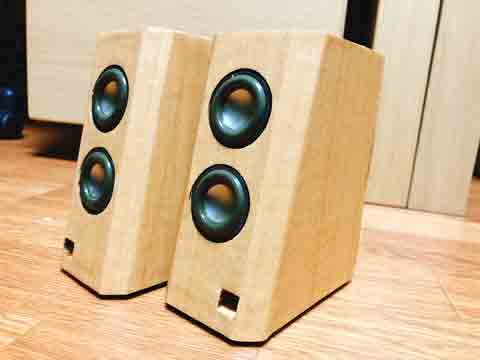
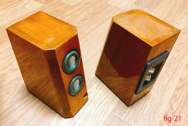
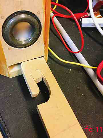
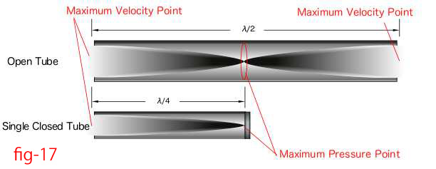
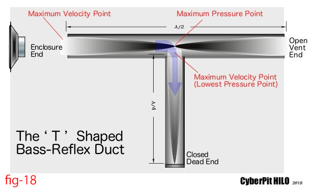
I used 12mm MDF for the front baffle and 9mm MDF for the rest of parts. Digging front baffle back, to mount the diaphragm as same surface level as front baffle. Vent is 9mm high and it’s width can adjust with small spacer plate.(fig-11) I made T-shaped resonant trap to kill the terrible pipe-organ resonant sound. (fig-17, fig-18) This works great as fig-19 showing. T-Shape vent design method is very simple, to attach a half of length single closed pipe at the middle of vent. A little bit wadding will reduce the resonant ringing sound of single closed pipe. After complete assembling, Surface finish material is urethane varnish (fig-21). But I cover them with wooden printed PVC sheet later.(fig-22) Inside the enclose was 50% filled with “Thermo-Wool” as a material of absorbing.
Crossover Design:
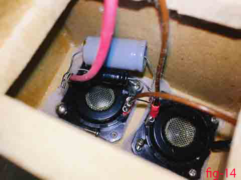
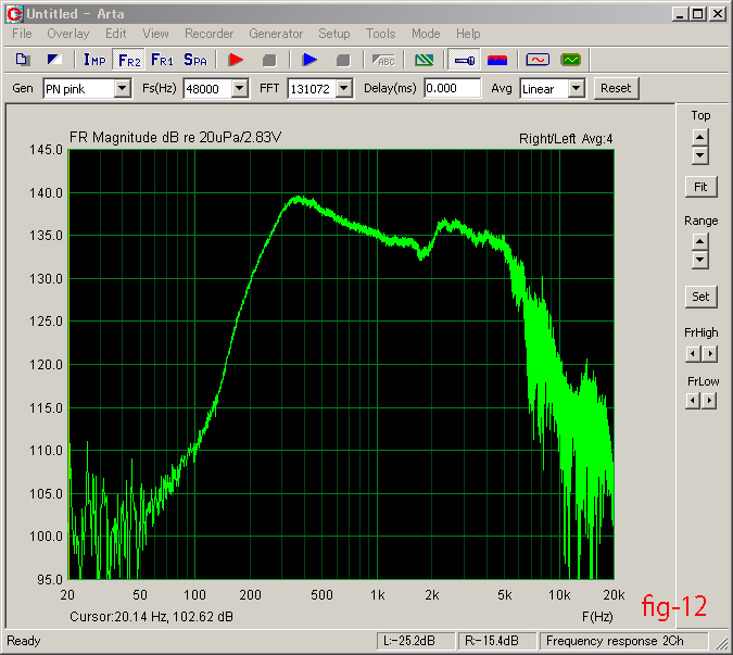
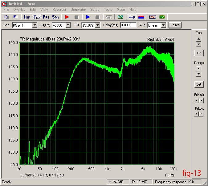
Upper side unit has parallel-connected 20uF capacitor to reduce the response above 2kHz. (fig-12, fig-14) In contrast, Lower side unit produce full range + upper unit-bypassed sounds. (fig-13)As a result of this, below 2kHz sound will be radiated both units, thus means +3dB gain will increase than higher range. A baffle step compensation required 6dB total.(fig-15) So the electrical 3dB L//R compensation circuit was connected in series. Total schematic circuit diagram will be found in fig-23. Overall system frequency response is fig-24. Overall impedance curve is almost flat and high enough to dive the most of amplifiers.
Tips & Tricks:
– T-Shaped Vent to kill the Pipe-Organ Resonances.
– Combined baffle step compensation (SP units 3dB, Electrical Boost 3dB, Total 6dB)
– Slant Baffle for the Desktop use.
– Printed PVC sheet to touch-up the bad finishing.
Conclusion:
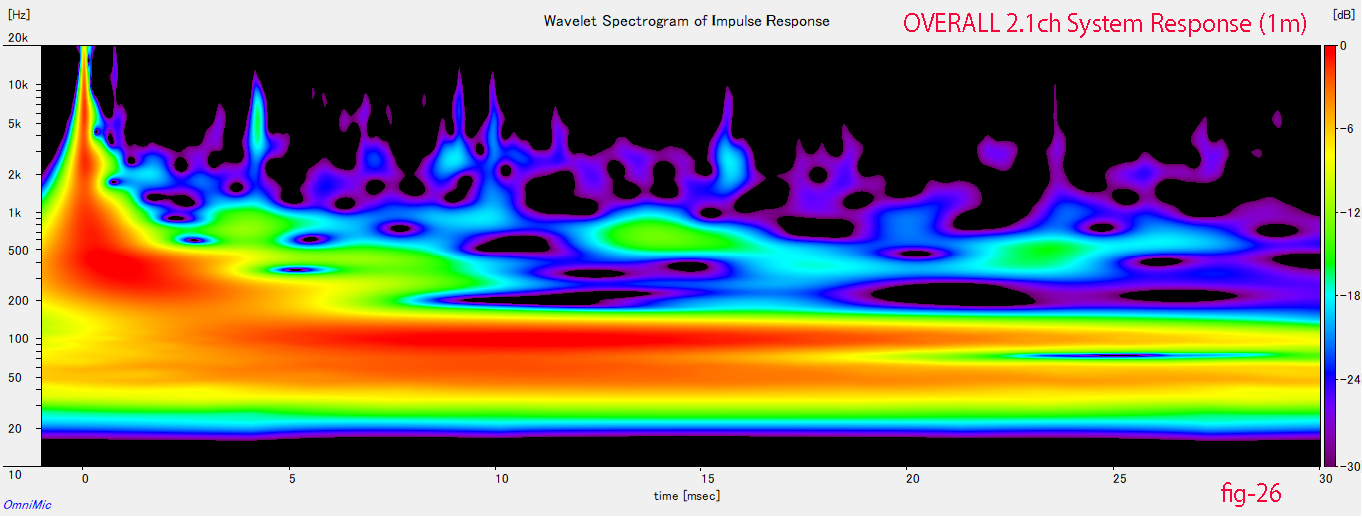
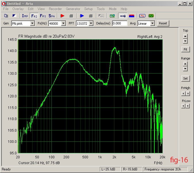
I was almost stacked with the terrible vent’s Pipe-Organ Resonances.(fig-16) But I could eliminate ringing sound with the T-Shaped vent. In the best case, over 25dB resonance can be reduced with this method. It’s easy to try using with T-Joint if you using PVC pipe in your project. As matter of fact, I could get coloration-less and smooth response sound from my vented enclosure.(fig-26)
About the Designer:
I have been interested in DIY Car and Home Audio over 20 years. My hobby project activities are stated in my homepage. You can search and visit my homepage which named “CyberPit HILO”. (Sorry, most of my pages are in Japanese)
Project Parts List:
|
Part # |
Description |
Qty |
|
296-250 |
AuraSound Cougar NSW1-205-8A 1″ Extended Range Driver 8 Ohm |
1 |
Interesting port – What does a/2 or a/4 mean?
thanks
What an interesting design. Looks real nice, and sure is compact enough. I like that you used the terminal cup as the ‘back’ of the enclosure, allowing enough room to attach the rear-mount drivers. Like the use of resonance trap–have seen it used before, but not on anything close to this small. Lots of ingenuity going on with these.
How do you feel they integrate with your subwoofer?
Cool project!
-TomZ