Centaurus


Designer:
David Hall
Project Category:
Tower Speakers
Project Level:
Intermediate
Project Time:
20+ Hours
Project Cost:
$100 – $500
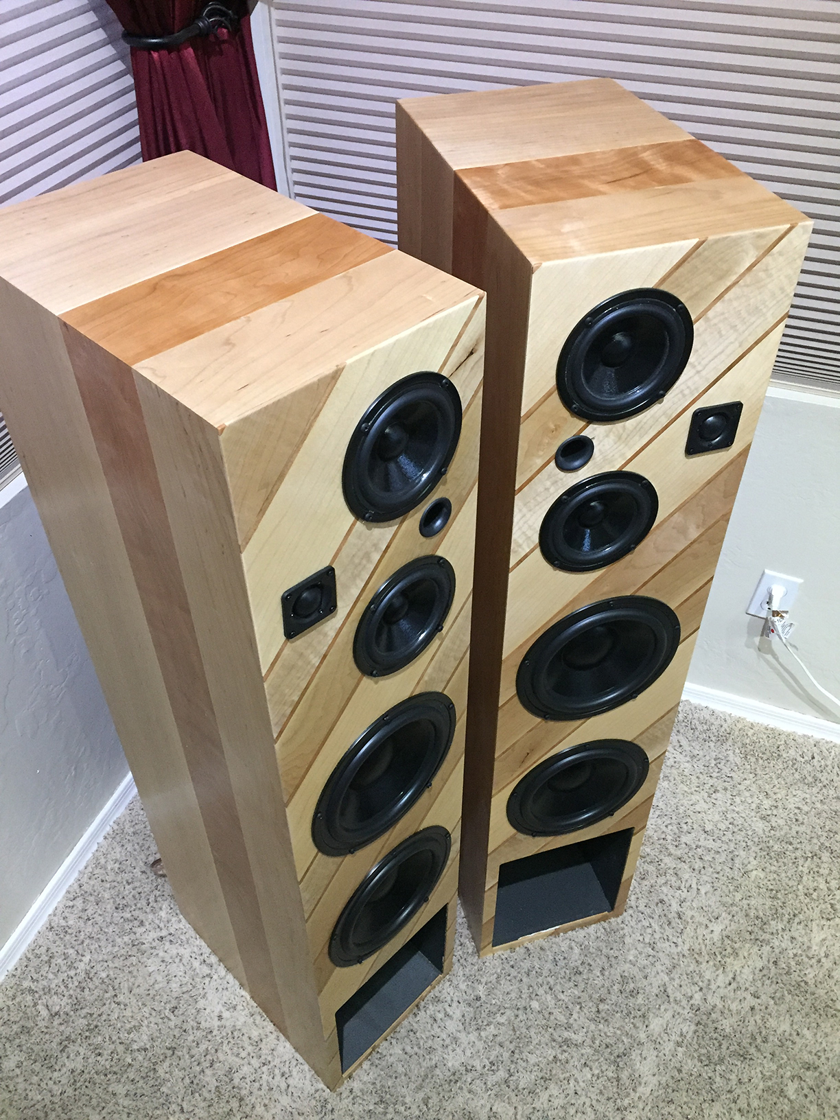
Project Description:
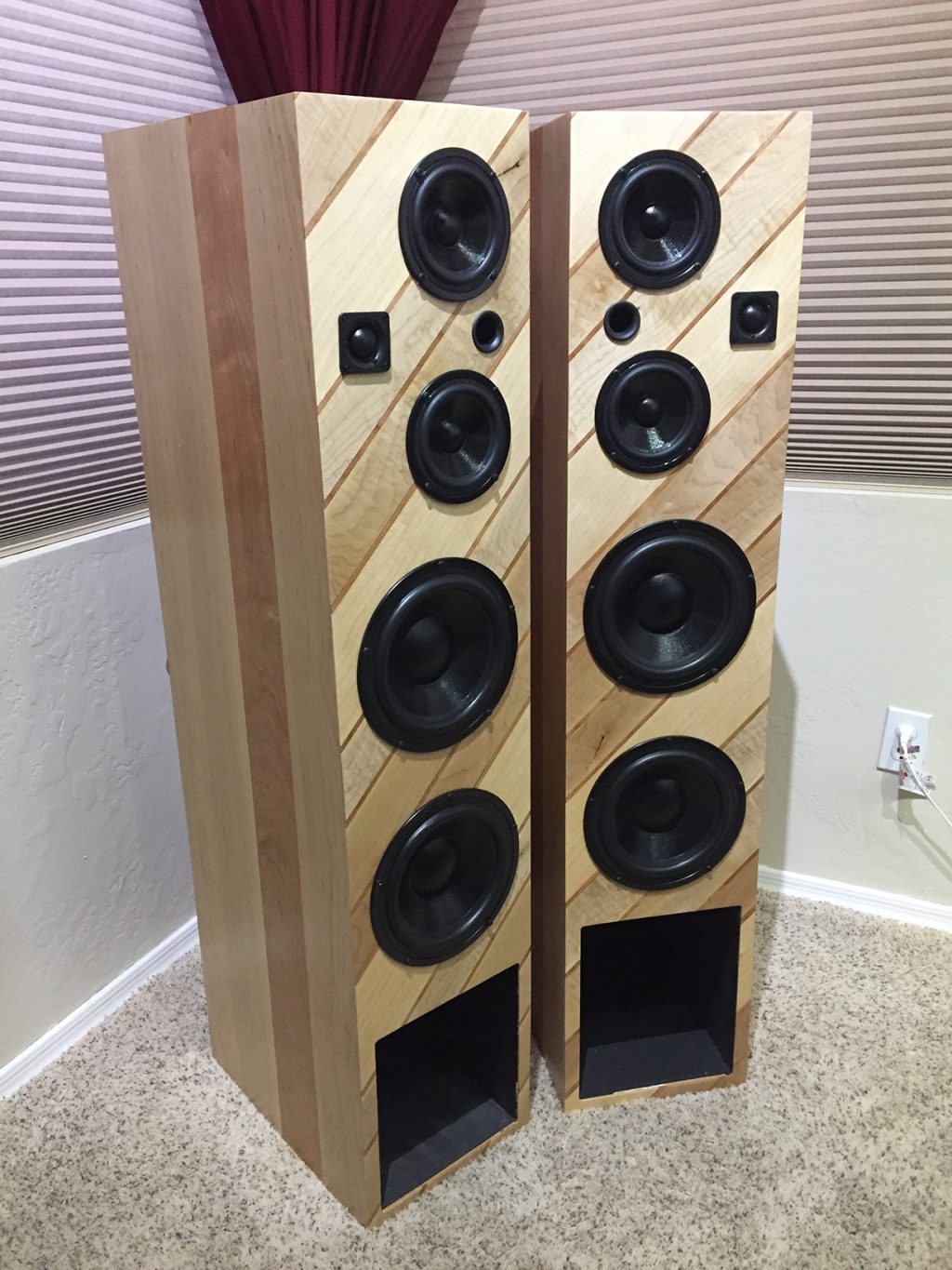
The Centaurus is a quarter-wave transmission line (labyrinth) speaker.
Design Goals:
1. Build a ¼ wave transmission speaker designed around 45 Hz.
2. Produce a solid and balanced low end at lower volumes
3. This initial build should be cost effective as this is a prototype for establishing an initial baseline performance of the enclosure, not the drivers. Future options will include higher end drivers as a function of customer budget and listening style of music.
4. Experiment with producing veneer vs. buying veneer.
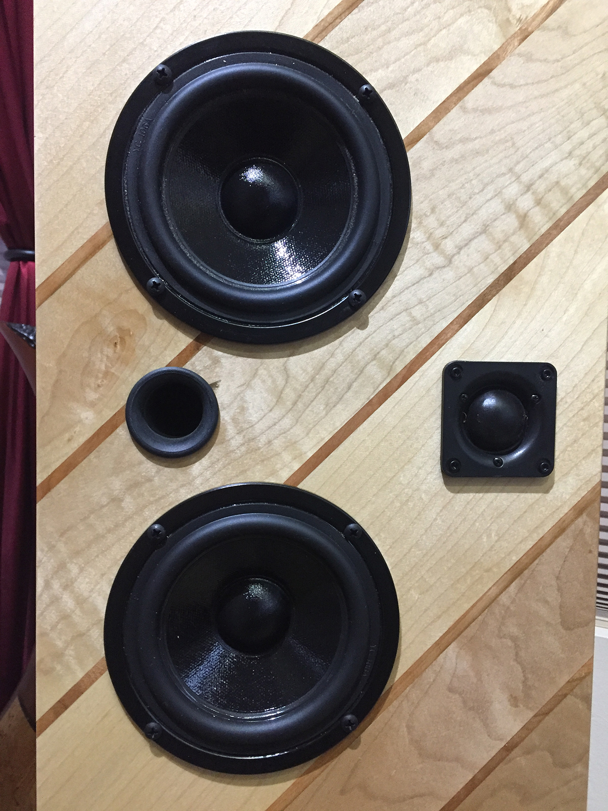
Driver Selection:
The MDT22 was selected as the tweeter because of its superior low-frequency capability (just in case it was needed it) as well as its power handling capability of 80 watts.
DS135-8 drivers were selected in part because of my experience with them, their power handing capability and modest price for this prototype. Other drivers will be considered in the final configuration, but the performance of the DS135-8 is excellent regardless of its modest price.
For the subwoofers the Dayton Audio SD215-8 8″ Designer Series Woofer Speaker was selected because it allowed for the wiring configuration that would yield a total of 8Ω for both subwoofers due to the dual voice coils. This was achieved by wiring the dual voice coils of each driver in series, then connecting both drivers in parallel. This tamed the subs bringing them into balance with the woofers.
Since distortion is proportional to displacement and displacement requirements increase by a factor of four each time the frequency falls an octave lower, woofers with extremely low distortion is needed for the Centaurus design. I needed all the piston area and movement I could get to maximize a lower dynamic range, minimize distortion and improve transient behavior. Using two drivers per speaker meant the woofers travel a much shorter distance and overshoot would be greatly reduced as pressurization and rarefaction occurs at the lower frequencies. The mutual coupling and boundary reinforcement enhance the radiation impedance effectively raising output and further reducing distortion. It is important to remember; multiple sub drivers can play just as softly or loudly as one sub; they just do it cleaner. The same applies to the DS135-8 mids.
Enclosure Design:
The enclosure design is a ¼ was transmission line configuration designed for a lower end of about 45 Hz. There are two separate chambers in the cabinets. The upper chamber is ported and houses the two DS135’s and the MDT 22. The main “chamber” is actually a folded labyrinth with the exit port at the base of the speaker.
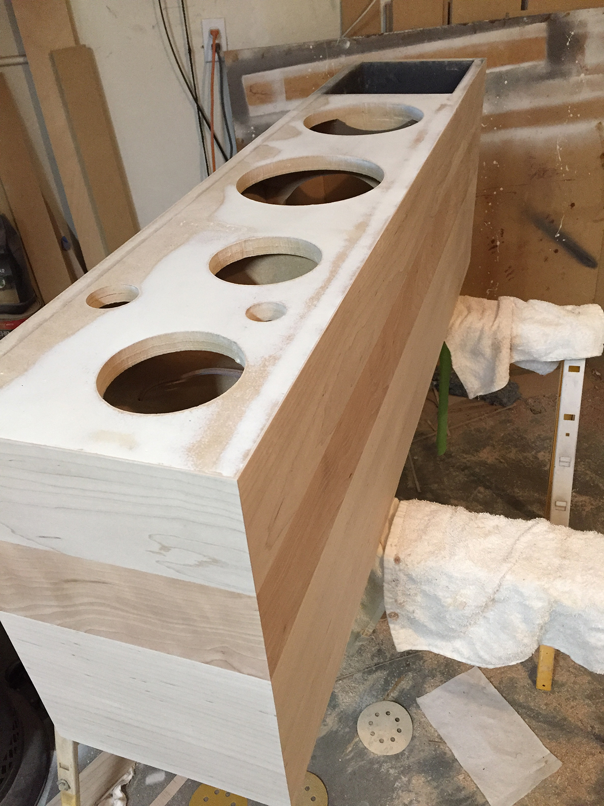
Enclosure Assembly:
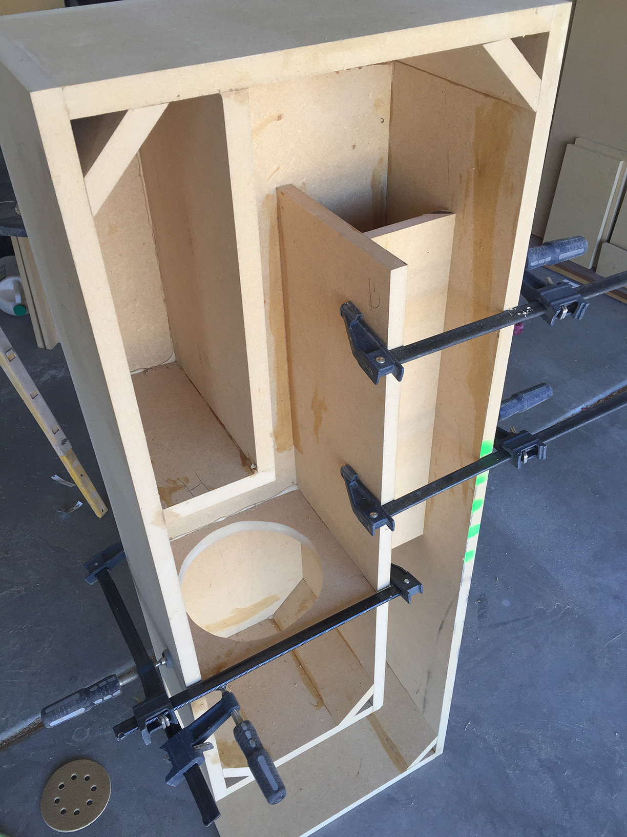
The enclosure is pretty straight forward using ¾” MDF, glued and screwed butt joints reinforced with window frames between the subwoofers and gussets at each turn. The gussets not only reinforced the cabinet but also “guide” soundwaves reducing corner refraction. The long baffle at the rear of the enclosure is supported by a strut running the length of the baffle to prevent any absorption of energy as well as provide structural support. The enclosures were constructed in one day, after which the countersunk screws were filled and sanded, and the cabinets were primed (which turned out to be a waste as I decided to veneer the units with maple and cherry wood since I had that material on hand).
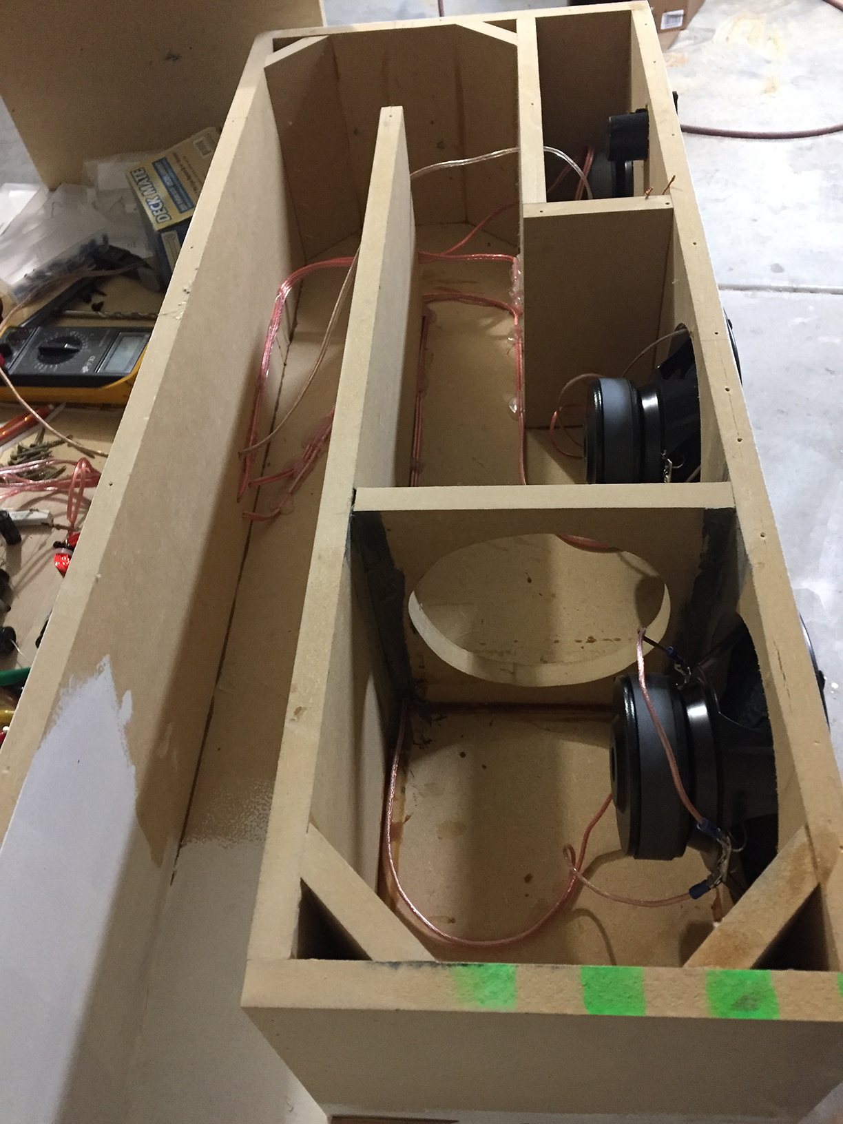
After the enclosures were constructed, they were wired and the drivers installed for initial testing using the prototype crossover. Initially, I installed 4” thick denim insulation to minimize back wave reflection off the rear of the enclosures, but the sound from the first speaker tested was very muddy. Instead, I used 2” egg crate acoustic foam and that resolved the issue. When the initial tests were complete, the drivers were removed and the side panels were permanently glued and screwed in preparation for veneering.
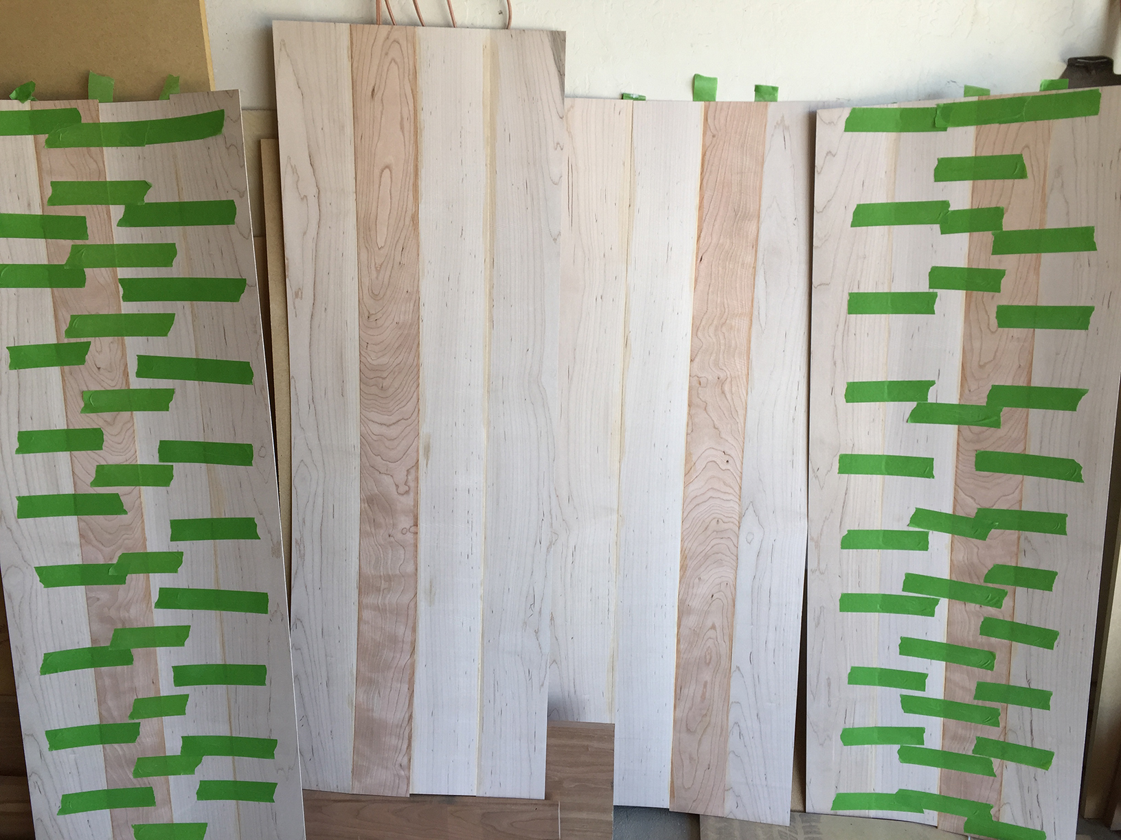
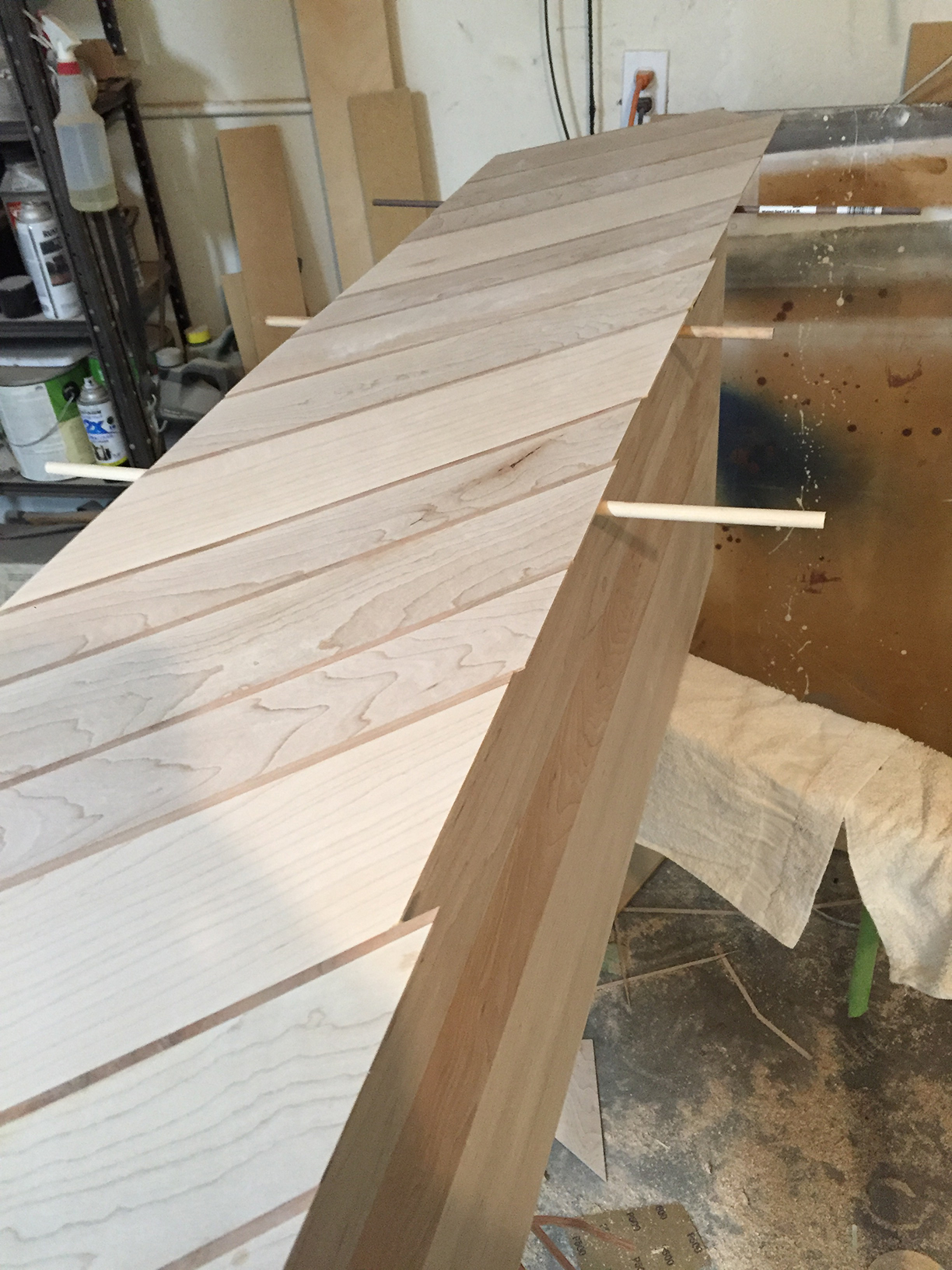
For the veneer, I used 8/4 maple and cherry lumber. The cherry serves as delineation accents in a random width diagonal pattern. I jointed, planed, then ripped the lumber then glued ¼” strips of cherry to the edge of the maple boards. The boards were ripped to a thickness of a little more than 1/16th inch in three arbitrary widths. After the veneer was ripped and sanded, random widths were glued together using Titebond III glue to make panels. The panels were again sanded to 220 grit then bonded to the cabinets using contact cement then trimmed flush with a trim router. The final pre-finish sanding was was sanded to a 320. I applied three coats of glossy polyurethane followed by one coat of semi-gloss poly.
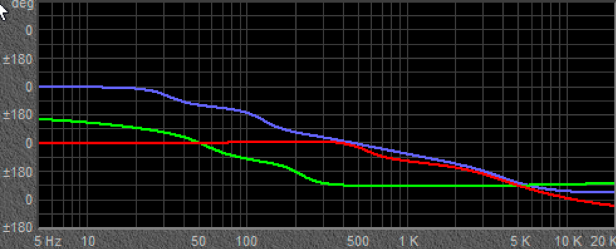
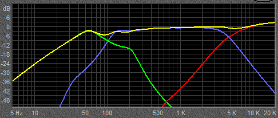
Crossover Design:
The crossover design is a combination of two 3rd order Constant Power filters for the mids and tweeter, as well as 125 Hz All Pass filter for the subs. The crossover was built for initial testing purposes only. The final configuration will be equipped with an 8-channel DSP for final testing, with installation and configuration completed at the customer’s site. A resistor was added to the tweeter to tame it a bit.
Tips & Tricks:
The cross-sectional area of the exit port should be roughly the same area as the combined subwoofer area. This would make the bass port smaller, lower the cabinet Fb and provide more appropriate back-pressure to the subwoofers, thereby reducing any likelihood of overdriving Xmax. The tweeter should have been installed such that the edges are parallel with the design of the front veneer. Also, the veneer of one speaker should will be flipped such that the diagonal lines are in the opposite direction. For esthetics the 1” port will be repositioned as well.
Conclusion:
1. The sound quality was significantly superior to expectations considering the modest cost of the drivers. Now I have a documented baseline for performance in upcoming versions of the Centaurus.
2. The next build will use purchased veneer. Considering the labor cost of cutting, gluing and sanding veneer, two rolls of 4’ x 8’ veneer would have been a smarter choice (but would lack the esthetic cherry bands that wrap around the cabinet).
3. A DSP/Amplifier will be used for subsequent builds as it provides for optimizing the frequency spectrum to the customers’ preferences and enables tuning/optimizing the speakers to the room in which they will be used.
About the Designer:
David Hall is an avid custom speaker and home theater designer. The favorite part of his job is speaker design and fabrication. His enclosure designs start with sketch pad and pencil. A lot of paper finds its way to the trash can before a design goes to CAD (computer-aided design). He pursues unique cabinet design and drivers that offer his clients both the look and quality of sound they desire. David’s philosophy is audio should be as pleasing to the eye as it is to the ear. It has to look as good as it sounds and it must sound awesome! David focuses on choosing drivers with optimal qualities to achieve the finest sound in order to diminish or avoid the electrical and acoustic challenges of crossover design. He has, in one way or another, been involve with electronics since he graduated from DeVry (decades ago). Music is a major source of enjoyment in his home. In his younger years David was a bass trombonist in jazz. He is a desert rat living in Phoenix, Arizona with his wife, Debbie. Occasionally, in the cool months, he enjoys a good cigar and bourbon (when his wife is not around).
Project Parts List:
pls give me box dimension