Dan’s SO1 A Solid Beginner Project
Designer: Dan Carroll
Project Time: 8-20 hours
Project Complexity: Hobbyist
Project Cost: $100-$500
Enclosure Design
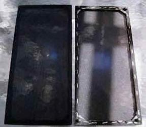
I originally planned to build a sealed box because I knew nothing about tuning boxes or porting. But as time passed and I read various posts, and worked on other boxes, I decided I could manage a ported box. Viperoni (Rudy) responded to a post I put up asking about port calculation, suggesting the flared port listed in the parts list. I messed around a bunch with PEBox and WinISD, and also looked at both Paul and Wayne’s 305/070 projects trying to determine box size. I also knew that because these speakers might wind up on a bookshelf one day, I had to front port them, which impacted the size of the front baffle and kept pushing me to a bigger box. I finally settled on around .52 ft^3. Playing around in WinISD, I came up with overall dimensions of 14.25″ H x 9″ W x 7″ D. The internal volume using these dimensions is .5195 ft^3, not accounting for an internal H-brace or the volume of the drivers themselves. In the past I had inset the baffles and was not that happy with the result, so this time I decided to glue the front and back baffles to the rest of the box, rather than inset them. This led to the following external dimensions (all 3/4″ MDF): front and rear baffles – 10.5″ x 15.75″; sides – 7″ x 15.75″; and top and bottom (which wound up being the inset pieces) – 7″ x 9″. I cut them on an old table saw my dad gave me years ago, after having finally gotten wise and purchased a rather inexpensive but serviceable Black and Decker carbide blade at Home Depot.
Amplifier/Crossover Configuration
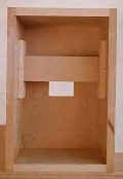
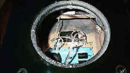
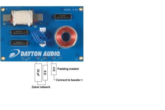
As I write this, I have yet to build my own crossover. I had ordered the stock Dayton 2000 Hz crossover when I first started on this project. As time went by, I learned about Zobel filters and posted a question about whether I should use one. PE Paul resoundingly responded “Yes” and gave me values, including a bypass cap. I had no need to place a PE order at the time, so off I went to Fry’s to buy the parts (see parts list). I never could find a .1 uF bypass cap anywhere, even later when I had reason to order from PE – that cap was backordered at the time. So, my Zobel is a simple cap + resistor unit. I soldered the cap and resistor together, Gooped them to a piece of Masonite the measurements for which did not keep, but around 1 inch wide and as long as the long side of the Dayton crossover. Those were soldered to positive and negative lead wires, one end to go to the crossover and the other end to go to the woofer. Initial listening tests disclosed a very harsh sounding tweeter. Wayne had already indicated padding the tweeter might be necessary, but I tested the speakers first without padding because I like bright highs. Bright, yes; harsh, no. So using twist-on wire connectors, I made a temporary tweeter pad putting a 3.9 ohm resistor in series with the positive tweeter lead and tested again. Much better! In final construction, the padding resistor was soldered to the positive tweeter lead and was Gooped to the H-brace. (See Picture – near the top of the woofer hole, you will see the white sandcast resistor glued to the H-brace.)
Enclosure Assembly
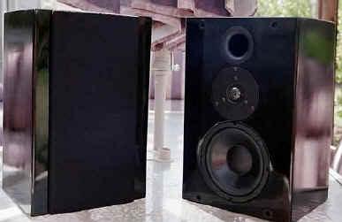
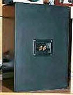
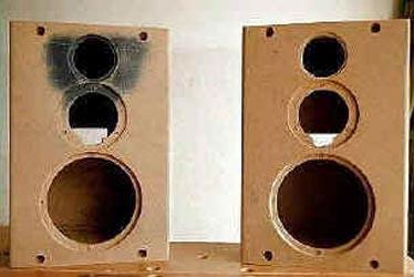
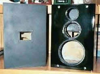
I also had to arrive at a visual design. At the time I was building these, I was toying with a different colored front baffle than the rest of the box. I had seen some speakers on a website somewhere with a narrow grille (grille of course required for SAF) and thought I would like the look with a contrasting front baffle. This required some space to either side of the drivers, that is, a design counter to the currently popular narrow-fronted speaker. I also wanted the grilles to be even with the top and bottom of the speakers. And I had to find someplace for the port. I understood then (and I now understand I may have been wrong) that the port should not be close to the woofer, so I put it above the tweeter, creating an inverted pyramid shape. Center-to-center from the woofer to the tweeter is 5 3/4″. I did not measure CTC for the tweeter to port, but because of space constraint, placed the port very close to the tweeter. The hole diameters were as follows: woofer – 6 9/16″ outer, 5 13/16″ inner, router depth for flush mounting 3/8″; tweeter – 4 7/16″ outer, 3 13/16″ inner, router depth for flush mounting 3/16″; port – 3 outer, 2 9/16″ inner, router depth for flush mounting 3/32″. I routered the holes in the front baffle using my Sears 1.5 hp router and a Jasper circle jig (both newly acquired for this hobby). I also routered the side edges only of the front baffle with a 1/2″ roundover bit before construction. I also constructed two H-braces, one for each box, out of scrap 1/2″ MDF for the sides of the H, and 3/4″ MDF for the cross brace, gluing with TiteBond II and clamping. They were from scrap and I forgot to take notes about them, so I don’t have dimensions, except I know the cross brace was 8″ long, and around 3″ wide. Below I will discuss the crossover and modifications to it. During box construction, I cut the hole for the speaker terminal cup with a jig saw, centering the hole on the back baffle, and predrilled the holes on the inside of the back baffle for installation of the crossover and add-on Zobel network, and on the outside for the terminal cup. I also screwed the crossover, Zobel, and terminal cup in at that time, then removed them again, so I would not have to “break in” the MDF later. I always install the crossover after all painting, so that the crossover does not get covered in sanding dust. I use hex heads because they are easier to install using my 1/4 inch ratchet inside the box after the box has been entirely assembled. I use 3/4″ black oxide screws from PE (see parts list) for external connections (drivers and terminal cup). Then I glued it all together, doing the back, top, bottom and sides at first. On all sides but the front, I used liberal amounts of TiteBond II, and then clamped the box. I also installed the H-braces using TiteBond II, locating them about 1/3 of the way down from the top, centered on the sides. I used no screws. (Picture shows the box assembled, with H-brace in place, but without front baffle.) After the glue set, I sprayed flat black spray paint on the brace and above it so no raw MDF would be visible through the port after assembly. Then I siliconed all the glued seams. For the front baffle, I put a bead of silicone along the inner edges and TiteBond II along the outer edges, and clamped the baffle in place. I did that because I used a round tube of silicone in a trigger applicator, and I knew it would be hard (more likely impossible) to get it inside after the box was glued up completely, especially with the H-brace in the way. The boxes seem to have sealed fine. At this time I also constructed the grilles, which I discuss separately below, and predrilled the pilot holes for the grille guides, and the holes in the grilles and cabinet for the insert and cup portions of the grill guides. (Two pictures above, the completely assembled boxes are shown). There is blue paint around one of the port holes because I had decided to paint the boxes blue to match a quilt in our bedroom, and thought I would need to install the ports before painting, so I “cut in” the port hole on one enclosure. Good thing; the blue was all wrong and abandoned in favor of piano black. I also decided I could wait until the end to glue in the ports, so I did no more cutting in. Also notice the notches in the tweeter holes for the tweeter terminals.) I wanted a grille which was both narrow on the face of the enclosure and thin in width. In my first two projects, using the Ford 6×8 speakers, I made grilles by cutting out pieces of 1/2″ MDF with a jigsaw, but I am notoriously cheap and hated the waste. So the next time (a center channel) I cut strips of 3/4″ MDF and glued and clamped them to make the grill. I intended to use a similar construction here. Since I wanted the grille thin, at first I tried to use Masonite, but it would not glue together well. So, I went back to 1/2″ MDF. For each grille, I cut two 1/2″ strips to length for the tall side, and two strips about 1 1/4″ wide for the top and bottom, less an inch in length to take account of the sides that I had already cut. I then notched the top and bottom pieces at an angle to make room for the grille guides, and glued them together with TiteBond II and clamped them. When they were dry, I ran them through the table saw with the blade as close as possible to the rip fence, which yielded a width just a little less thick than the length of the grill guide insert press fit pieces. I think the width was a little less than 3/8″. Then I routered the front edges carefully with a 1/2″ roundover bit, with the router mounted to a small tabletop router table. Next I clamped them to the enclosures (which were not yet painted) and drilled guide holes with a small bit from the outside of the grilles into the enclosure, so that the grille guide inserts and cups would line up exactly when all work was done. Then I drilled 3/8″ inch holes for the grill guide inserts (which were sanded down a little to cut down on length), and painted the front and edges flat black, so the MDF would not show through the black grille cloth. *For complete instructions view the PDF below.
Conclusion
I know it’s not Oscar night, but I have to thank PE Paul, Wayne Jaeschke, Viperoni, and other folks whose names I neglected to record who posted responses to questions; Parts Express for selling good stuff at reasonable prices and for hosting such a great message board; my dad for the table saw; my wife for helping with the grilles (as well as all the other obvious mushy stuff); and my son for helping with the name.
About The Designer
Dan Carroll is an attorney who is nearing 50 but knows he is not 14 years older than he was when his son was born, nor 6 years older than when his daughter joined the family through international adoption, and certainly not 16 years older than the day he took his wedding vows. He specializes in energy issues, which means you can blame him for the energy mess in California if you wish – he sure should not be running an old table saw and a new router putting load on the system in present circumstances! He lives with his family and a golden retriever/chow/spaniel mix named Beauregard Emanuel Carroll in a small suburb of California’s fair capitol city. When he is not working, spending time with his family, reading Tech Talk and speakerbuilder.net, working, building speakers and listening to music on them, working, watching his son’s Dixieland jazz band perform, eating too much, or working, he sleeps.
Project Parts List
|
Part # |
Description |
Qty |
|
275-070 |
1 |
|
|
295-305 |
1 |
|
|
260-140 |
1 |
|
|
260-402 |
1 |
|
|
004-4 |
Dayton Audio DNR-4.0 4 Ohm 10W Precision Audio Grade Resisto |
1 |
|
004-6 |
Dayton Audio DNR-6.0 6 Ohm 10W Precision Audio Grade Resisto |
1 |
|
027-350 |
1 |
|
|
260-280 |
1 |
+ There are no comments
Add yours