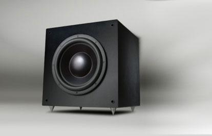
RS1200
Designer: Anonymous 1
Project Time: 1-8 hours
Project Complexity: Hobbyist
Project Cost: $100-$500
Driver Selection
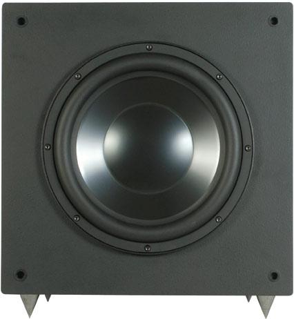
I selected the Dayton RSS12HF-4 because it is one of the most popular subwoofers we offer, and the 12″ cone is a desirable size for producing adequate bass for home theater systems while being musical enough for stereo playback. With proper loading and amplification it will meet virtually any reasonable expectation in terms of sound quality and low frequency output. It features three short circuit paths, an extensive vented motor structure, and a 2-layer coil for reduced back EMF.
Enclosure Design
The first step in speaker enclosure design is obtaining accurate driver T/S parameters. This gave me the chance to use the new Dayton WT3 woofer tester. In less than a minute I had what I needed and was ready for box design. Using Winspeakerz speaker software, I imported the parameters from the WT3. Although this driver models well in both vented and sealed type cabinets, I chose the sealed version with an optimum volume of 1.6 cu. ft. and an f3 of 38 Hz. After taking into account the volume displaced by the driver and the amplifier, I was looking at a total volume of 2 cu. ft. It dawned on me that we offer a cabinet of that size, complete with cutouts for the driver, amp, and spikes in the Dayton 12″ Titanic kit.
Amplifier/Crossover Configuration
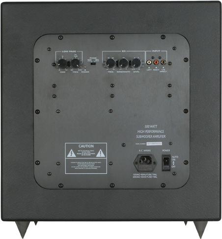
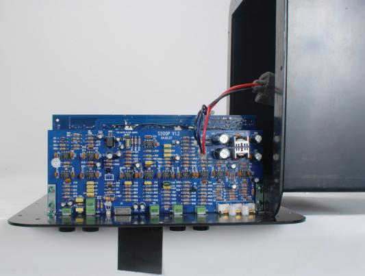
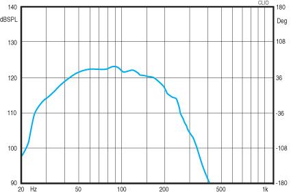
I took nearfield measurements, which is standard practice to properly measure subwoofers, to help negate room reflections. I was looking for the lowest f3 with the flattest frequency response. I first wanted to get a starting point (reference) so I measured the response of the driver-amp system with the crossover setting at maximum and no equalization. Looking at the graph below the f3 was around 40Hz. A little known but useful feature of the Dayton HP (high power) amplifiers is the 6 dB notch filter, which was added for the Titanic kits to help flatten their frequency response. Next I measured the system output after adjusting the amplifier settings to create the lowest f3 and flattest response curve, with the notch filter disabled (Red). I achieved a relatively flat response with an f3 of 30 Hz. I noticed a peak in the 50-60 Hz range and because of this peak I thought the complete system might also benefit by enabling the notch filter. I measured again with the notch filter enabled and after some tweaking was able to achieve a relatively flat response with an f3 of 25 Hz (Blue). Red Response – Output of the amp-driver combination with notch filter disabled, crossover set at 100 Hz, and with parametric EQ settings of: Frequency = 25 Hz Bandwidth = 0.20 Level = +6 dB Blue Response – Output of the amp-driver combination with notch filter enabled, crossover set at 85 Hz, and with parametric EQ settings of: Frequency = 25 Hz Bandwidth = 0.27 Level = +6 dB Note: To compare measurements of notch fi lter enabling vs. disabling, I found it easier to remove the rear enclosure from the amp and mount it separately in the cabinet. This allows easy access to the jumper while maintaining the integrity of the cabinet for measurements. The choice is yours, to notch, or not to notch. With plenty of power available, I feel the tradeoff of a little efficiency for a lower f3 is worth it, so my choice is with the notch filter activated. Note: The default factory setting of the notch filter is “disabled”. To enable the notch filter, simply switch the position of this jumper (connect left and middle pins.) Here are the measurements of the amplifier’s output with the notch filter enabled (Blue) and disabled (Red).
Enclosure Assembly
The enclosure is constructed of precision CNC cut 3/4″ MDF then assembled with polyurethane glue for superior strength. An internal brace is also utilized to minimize cabinet resonances. The enclosure is pre-drilled and cut for the amplifier,driver, and spikes, so after some assembly (an hour or so), this is essentially a plug-n-play system. The easy assembly went as follows: cut and apply 2-1/2″ foam to all internal panels, mount the amplifier, connect and mount the driver, and insert spikes.
Conclusion
This subwoofer system produces tight, clean bass from any source. Adjustments to volume, crossover frequency, bandwidth, and more, are easily accessible via panel controls. The amplifier along with a high-excursion, low-distortion driver and a solid MDF cabinet, will ensure clean, detailed bass, even when you crank up the volume.
Project Parts List
|
Part # |
Description |
Qty |
|
295-464 |
1 |
|
|
300-807 |
1 |
|
|
302-812 |
1 |
|
|
240-715 |
1 |
|
|
260-776 |
1 |
|
|
260-515 |
1 |
+ There are no comments
Add yours