
Low Noise Cables


Designer:
John Hollander
Project Description:
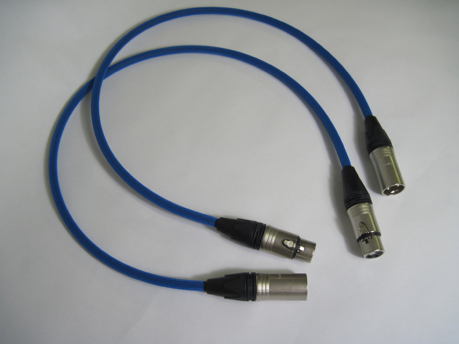
This project makes 2 low noise interconnects from a preamp to an amplifier.
Design Goals:
I noticed some noise from my power amplifier the other day which lead me to investigate making some new interconnects. There is information on the web showing how Star Quad wiring reduces the noise on the microphone cables, which is ideal for interconnects between a preamp and amplifier.
Driver Selection:
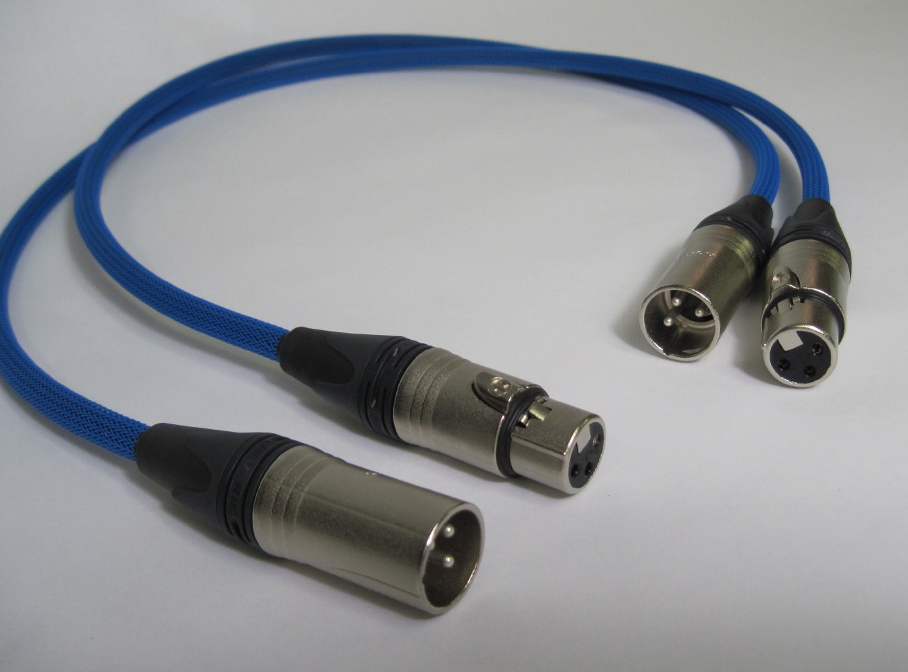
This project uses “Balanced” connections between the amplifier and preamp. Balanced connections have 3 wires and use XLR end connectors.
Parts Express carries Belden’s Star Quad cable. This cable has the 4-conductor twisted pair wires and the braided outer sheath required for Star Quad cabling.
Neutrik male and female XLR connecters were also used.
Enclosure Design:
Cable protection
Left alone the black Belden cable insulation would look like any other interconnection cable. As these cables are “special”, they are covered in blue Techflex Braided Sleeving.
Enclosure Assembly:
Cable Assembly, Sequence of assembly
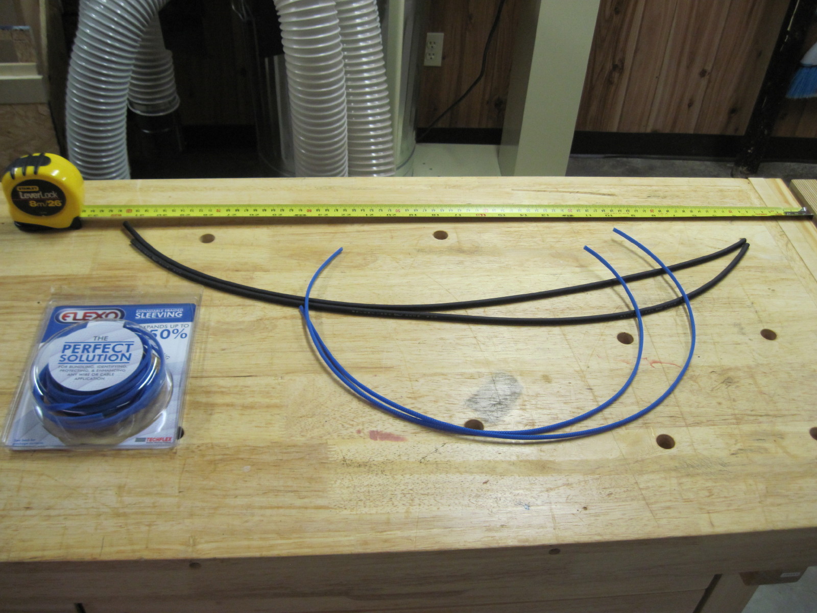
Measure or mock up interconnection wire length. Leave an extra about 5 cm of wire to enter each connector. Cut wire to length.
Measure and cut the Techflex about 5 cm shorter than the length of each wire.
Push the Techflex on the cable. The technique can be seen on You Tube. The sequence is with hand-1 hold the cable; push the Techflex on with hand-2; Hand-2 pinches the Techflex and
cable together creating an expanded bubble of Techflex over the cable; Hand-1 release the cable allowing the Techflex to collapse and move down the wire.
Center the Techflex on the cable. You will notice the Techflex will be shorter than its original length.
Use about a 4 cm piece of heat shrink tubing to secure the ends of the Techflex. Center the heat shrink tubing half on the cable and half on the Techflex. Use a longer piece of heat shrink tubing if you want the tubing to show outside of the Neutrik connector.
Slide on the Neutrik connector ends. The hard plastic wire clamps are split and can be added over the wire later. They are difficult to move over the Techflex.
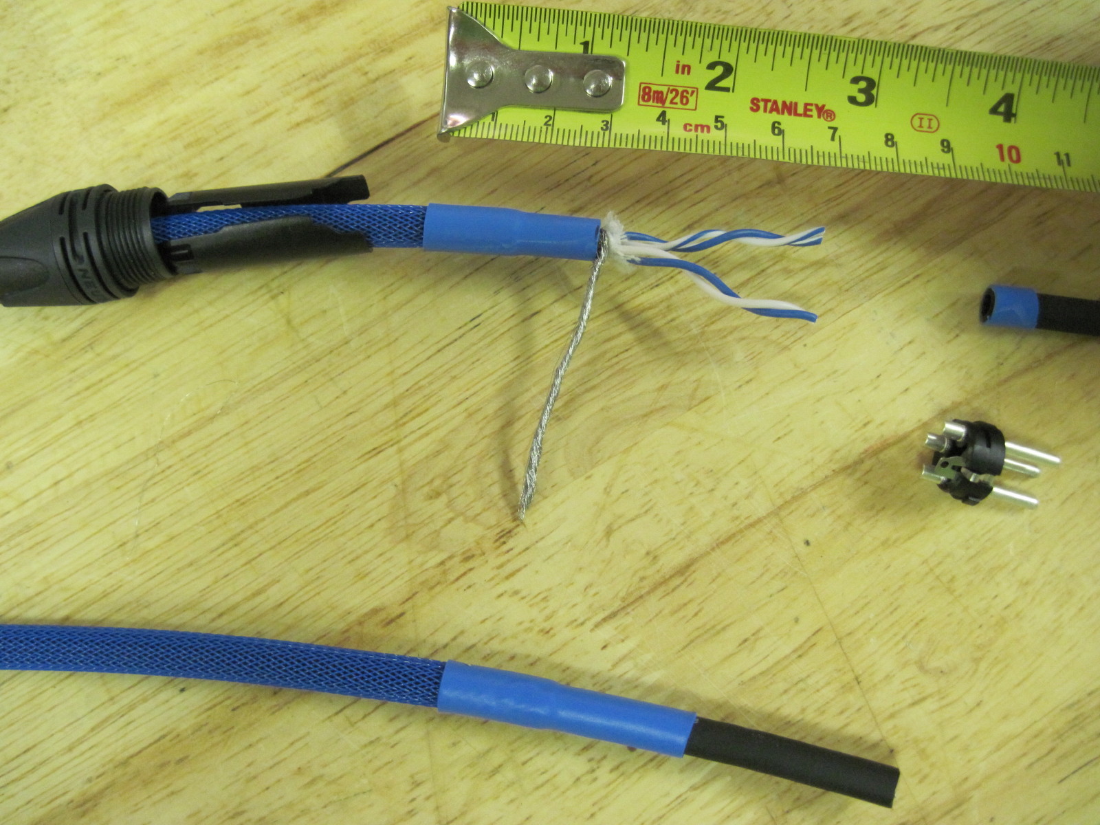
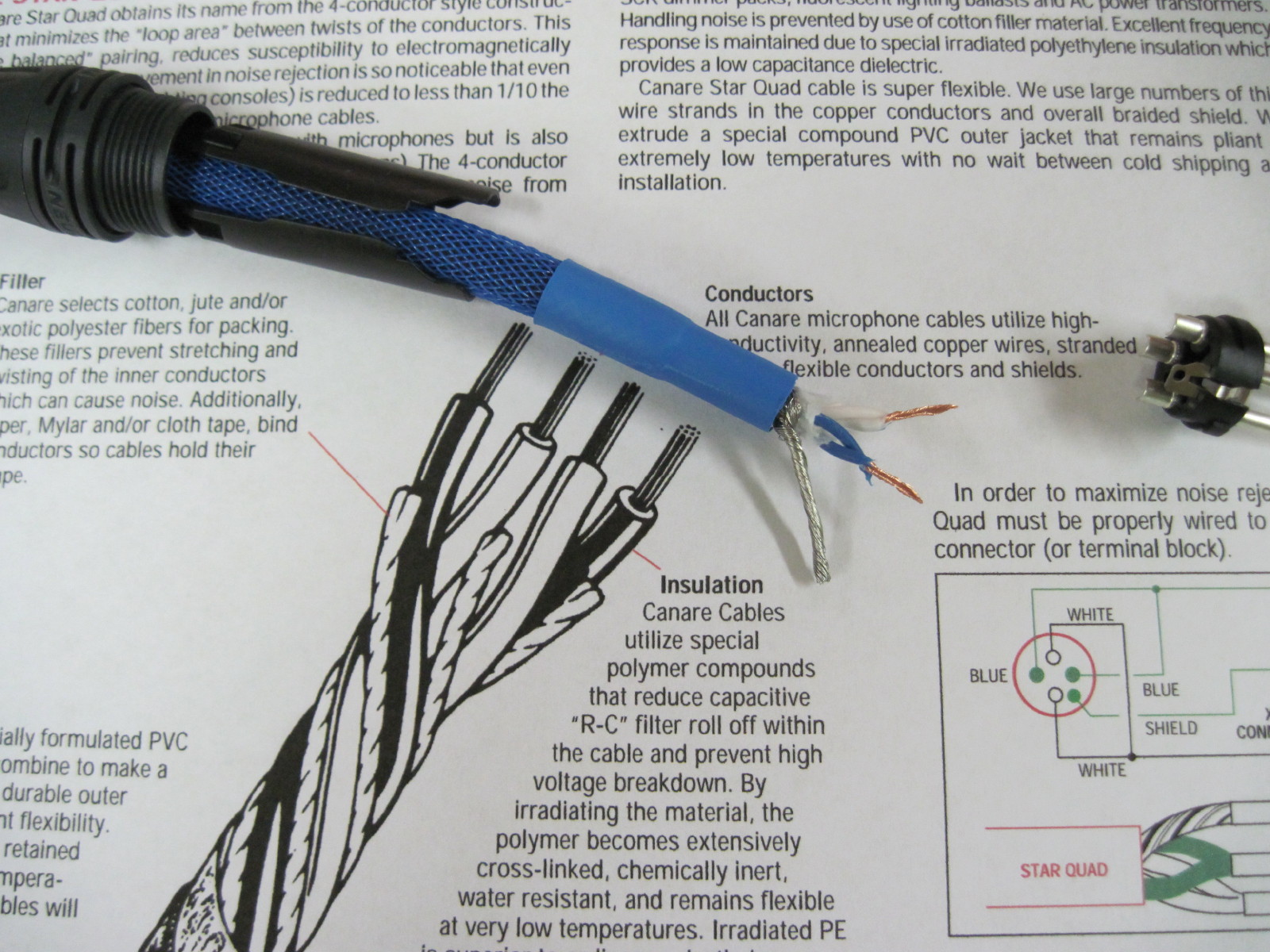
Cut the Belden wire insulation and heat shrink tubing down to the wire braid. The wire braid is easily cut so be careful as we need the braid. The pictures show cutting the heat shrink plus cable to a length of 3 cm.
Remove the insulation. Unravel the wire braid using a pointed tool. Twist the wire strands together to form the ground wire. Cut the paper and strings from the cable and unravel the twisted wires.
The twisted cable pairs are mostly blue and mostly white. Straighten the wires. Cut all the wires including the new ground wire to a length of about 2 cm.
Strip about 1 cm of the 4 insulated wires. Twist together the mostly blue wires, then twist together the mostly white wires. You should now have three connection points; bare Ground wire, mostly Blue wire, and a mostly White wire.
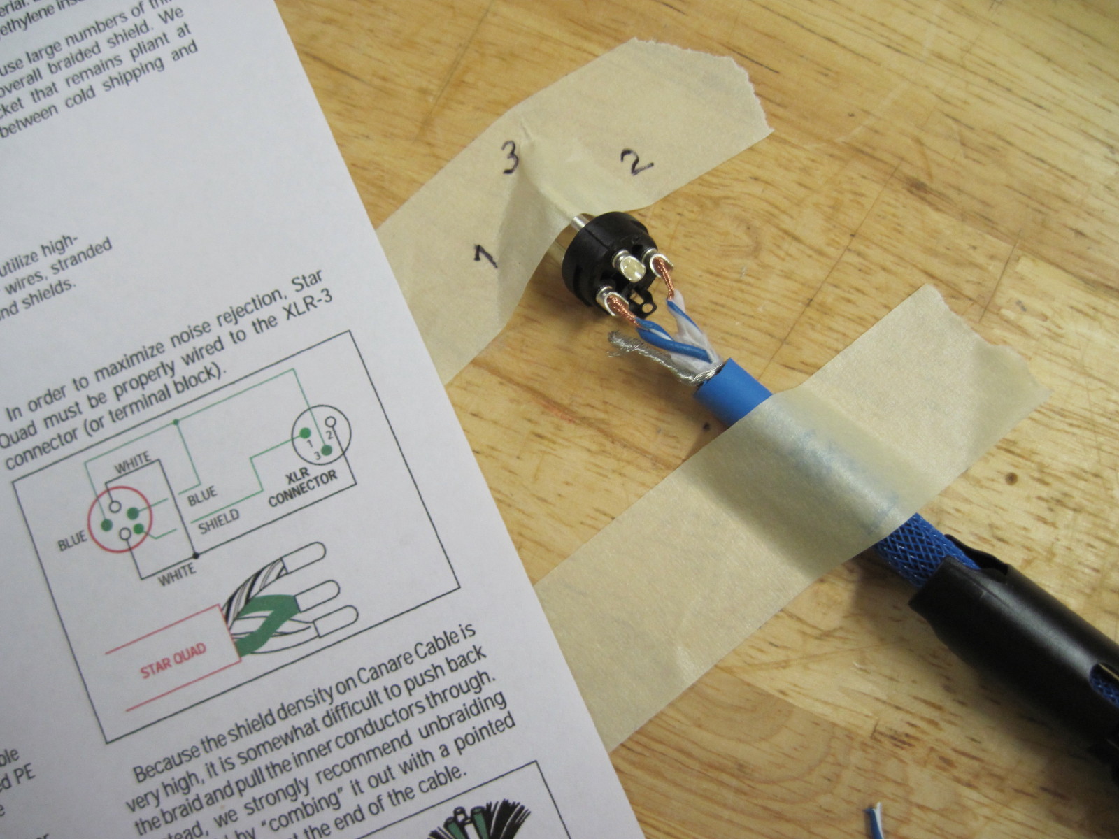
Inspect the Neutrik connectors and notice the terminals are labeled 1, 2, and 3 on both the male and female ends. Solder the Ground wire to #1, White wire to #2, Blue wire to #3. Inspect the connections to ensure no small wires are loose.
Straighten the wires, snap over the wire the Neutrik internal plastic wire clamp. Slide down the Neutrik top cap and screw into the connector end.
Crossover Design:
Use an electrical meter to check that the connector pins and receptacles are connected correctly.
Products Used
Part # 092-304 Neutrik NC3FXX Male XLR Connectors
Part # 092-307 Neutrik Female XLR Connectors
Part # 102-1270 Belden Brilliance 1192A 24 AWG 4C Star Quad Mic / Line Cable
Part # 082-328 Techflex 1/4″ Expandable Sleeving
Tips & Tricks:
Leave enough room to strip the wires.
It may be helpful to trim the bare wires after they are twisted together.
Use masking tape to hold items steady so they can be soldered
Use kitchen jar opener sticky pads to hold and screw the connector pieces together.
About the Designer:
I’m a former design engineer turned manager, so I use speaker building as a creative outlet. I have been building speakers for 15 years+
I wish i could buy a pair!
A friend pointed out that it looks like the blue wire is attached to the #1 terminal in the picture. The blue wire should be attached to the #3 terminal.
The picture is deceiving, the blue wire landed in the wrong location while soldering the white to the number 2 terminal.