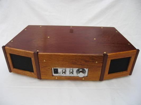
Sound Wave Guide Table Radio

Designer: Den Hobbyist Woodworker
Project Time: 20+ hours
Project Complexity: Hobbyist
Project Cost: Under $100
Overview
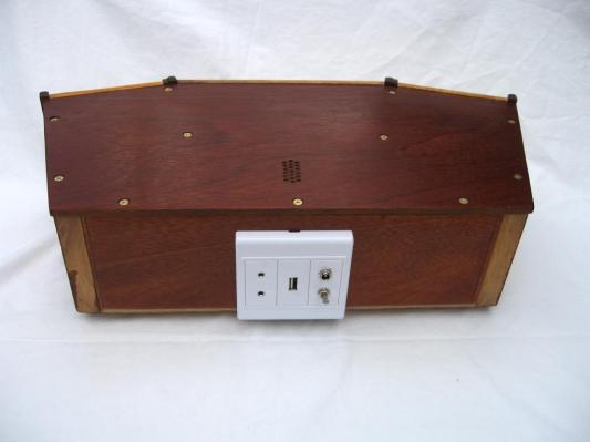
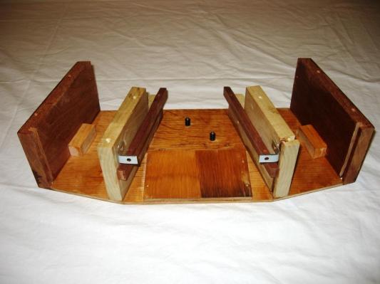
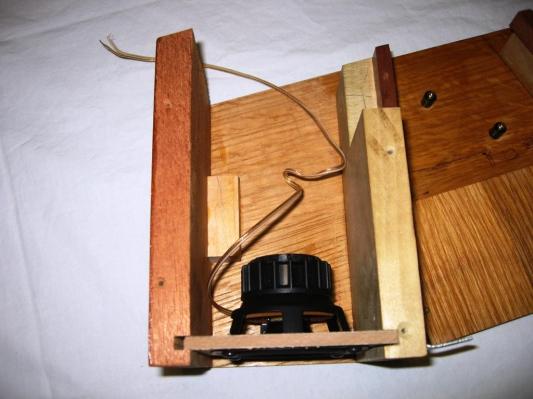
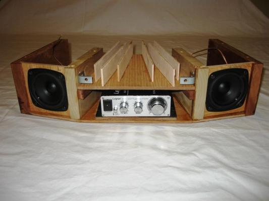
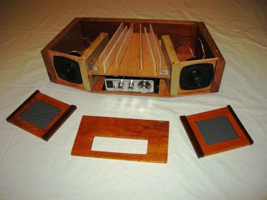
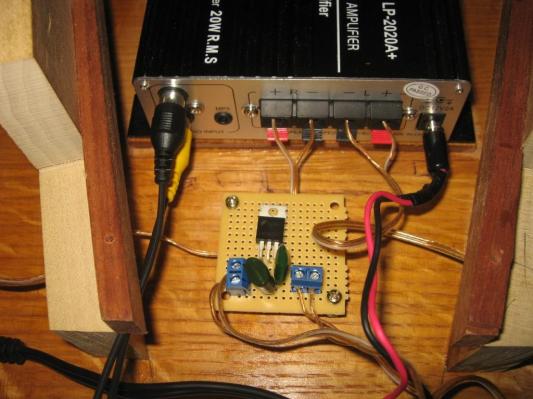
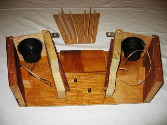
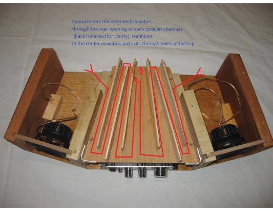
I wanted some “background” music instead of the “upfront” sound of the primary stereo system and after buying my Mother a Bose Wave Radio several years ago and listening to it fill her small condo with sound, I looked at buying a used one for our internet radio devices. Used because I did not want to spend the nearly $500 for a new one. I was pleasantly surprised to see that even used Wave Radios were still commanding prices of several hundred dollars; more than I wanted to spend. Having been a customer of Parts Express over the years and being a woodworker, I said to myself: “I can make one out of wood”. So with a little research on the Parts Express website and one of my favorite China mail order gadget dealers, I settled on the small LePai TA 2020 amplifier and 3” Tang Bang W3-1053SC Full Range Drivers. Knowing the dimensions of the hardware, I made a scaled sketch and then make a crude paper model to conceive the overall dimensions of the radio. Starting with the bottom made from ¼” oak plywood, I developed the rest of the structural and functional aspects of the design from there. I selected mahogany for the sides and back, Mahogany veneer over the oak plywood for the top and poplar for the interior support walls. Red oak comprised the face plate and the grill frames and the grills are perforated steel sheet painted flat black. The speakers were mounted on ¼ “plywood with a 3” cutout in the center. I wanted to be sure I could assemble the components and the radio in steps and that it could be taken apart for modification or repair. That inspired the simple mounting of the speaker assemblies in channels (dados) in the sides and center support frames that defined the primary speaker chambers. In the lower center compartment, I included the circuit for a 5volt step down power supply tapped into the 12 volt amplifier supply and terminated in a popular USB connector for the phone devices to be charged. I also took to the rear of the radio, the direct line in and MP# connectors of the amplifier as well as the main power connector. Again, the idea of assembly and disassemble were the motivation of not hard wiring these components. The second level of the center section comprises the extended sound chambers or “wave guides” of both the right and left speaker. While very crude and made from thin craft plywood, they do send sound (measured by air movement) out the top holes in the radio centered on the middle combined sound chamber. I have no audio measuring equipment and used no actual “design” calculations that I have used on other speaker projects, so I let my ears determine effectiveness of the wave guides and of having the top in place. The movement of a tissue placed over the sound holes bored in the top confirmed the escape or sound and air movement. I did use some weather stripping on the top edges of the sound chamber dividers along with silicone sealant along the seams of the speaker assembly dados in a crude attempt to isolate the sound guides and improve their functionality.
About The Designer
I am a Risk Management Consultant who has been an electronics nut since I was 5 years old (1960) inspired by my dad who helped me build my first crystal radio back in the day. I started woodworking 20 years ago and have made projects large and small having my work published in several books and magazines. I am known as ” Dennis the Hobbyist Woodworker”.
I have been brainstorming my desktop stereo for weeks now and have been trying to put my technical thoughts into a form. And for weeks I have been struggling trying to do the translation, until I saw this and immediately knew that this is what I had been trying to imagine. I applaud you! Amazing!
I will be using more drivers in my design. Stereo but also thinking of a highfi center channel. I have even considered mounting a subwoofer pointed downward in the center of the unit and creating a second transmission line. Nice work!