DAYTON SUBWOOFERS
Designer:
WARREN HAGAN
Project Category:
Subwoofers
Project Level:
Beginner
Project Time:
8-20 Hours
Project Cost:
$500 – $1,000
Project Description:
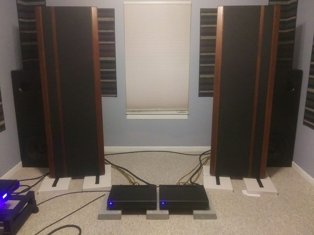
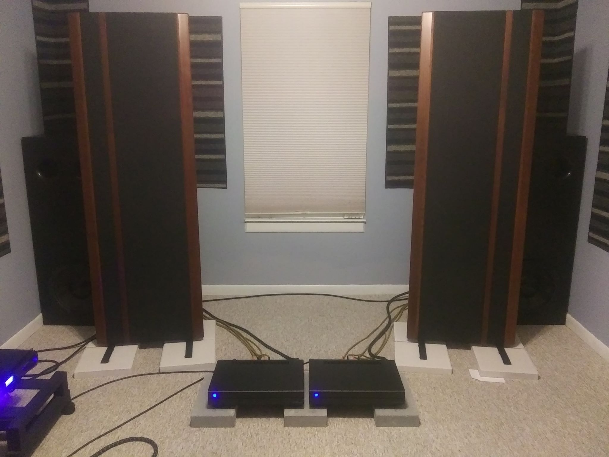
Large ported stereo subwoofers for music system
Design Goals:
Add some low end weight and punch to stereo speakers lacking in this area. Lots of headroom and ability to reach down to 20 hertz with authority and have a small footprint in the listening room
Driver Selection:
Dayton RSS390HF-4 15
Enclosure Design:
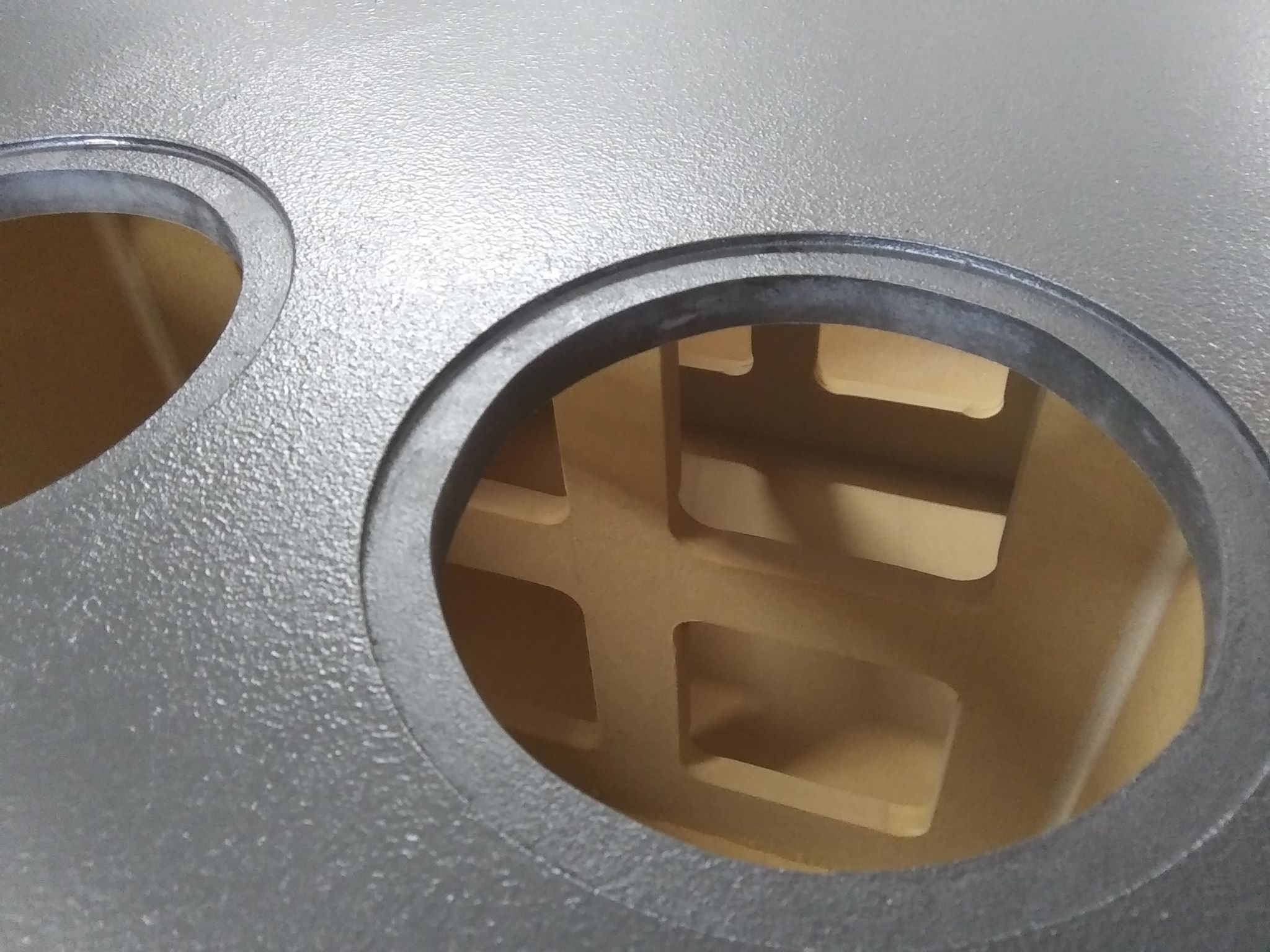
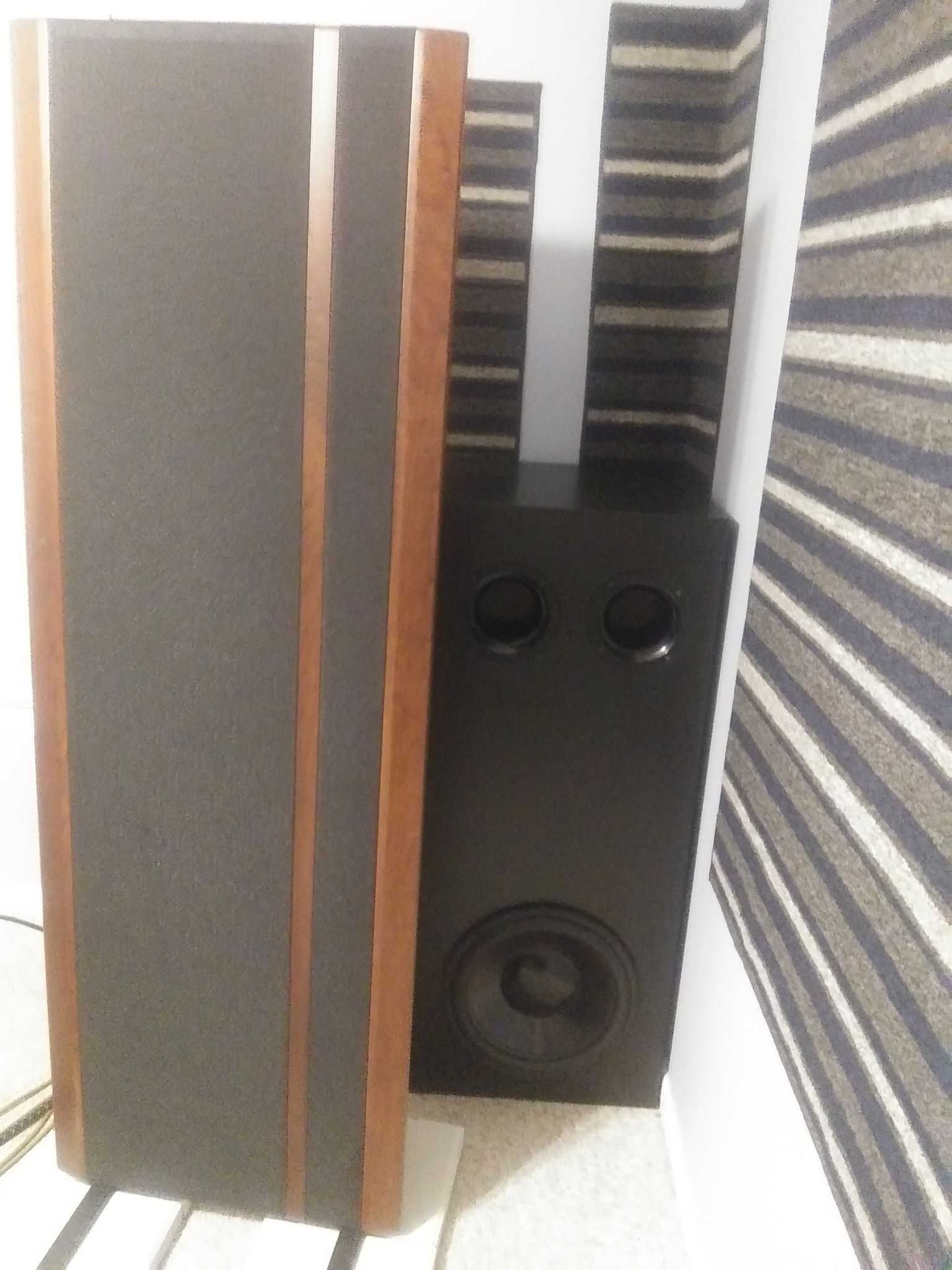
Vented 9.4 cubic feet with (2) four inch ports six inches long. Small footprint
Enclosure Assembly:
3/4 inch MDF built using wood glue and 2.75 inch hex head #6 wood screws every four inches. One inch poly foam on all interior walls, all seams caulked. Routed edges for the ports so their flanges are flush with the baffle. Black electrical tape placed around the edge of prt opening for an airtight seal with the cabinet. Two coats of black acrylic semi-gloss paint. Screw in rubber feet one inch from the edges on each corner.
Crossover Design:
Electronic
Tips & Tricks:
Two great options for the crossover and EQ / Bass Boost are pair of the Dayton SA1000 Subwoofer amplifiers Part #300-811 or a Behringer ULTRAGRAPH PRO FBQ1502HD Part #248-6945 with a Crown XLS DriveCore2 Amplifier Part #245-510 driving the subs in stereo. The Behringer EQ has a great subwoofer crossover and good control of the frequencies down to 24 hertz. The Crown amplifier has adjustable input voltage so it will work well with consumer grade stereo equipment and the subwoofer outputs from a surround sound receiver or processor. The Dayton amps draw a little more from the wall but produce powerful sound and they offer good boost and low-cut protection to avoid damaging the subs. The Crown was bench tested by Audio Science Review and produced 700 watts continuous in stereo at 4 ohms with a 50 hertz signal which is amazing for any amp regardless of price. The fans are silent. You can also use the less expensive Crown XLS 2002 with great results. Set the gains on the Crown and Behringer to 12 o’clock and the make adjustments while testing to get them to your desired sound levels.
Conclusion:
Build enclosure exterior dimensions, cut one hole in rear for terminal cup. Divide the inside of the enclosure into thirds and place two sections of braces made from 3/4 MDF from front to rear and from left side to right side horizontal with the floor if the cabinet were standing upright. You can also use 2 by 4’s for the braces if building the braces from MDF is too difficult. Make sure you use a minimum of 5 wood screws for each seam on all sides of the cabinet, including the braces. This increases strength and prevents possible rattles during high volume listening sessions. Overkill is always better, do a little more than you think you will need because you probably will not be able to reinforce the enclosure later. Glue is not sufficient for these enclosures even if you let them sit clamped for several days. For even more nert enclosures, use two pieces of MDF on the front baffle. Cut two holes from top and evenly spaced apart. Cut 14 inch circle opening for driver from bottom and centered on front of baffle. Use several clamps when glueing and leave the clamps for at least 2 days. I left mine on for 3 days. remove the rubber and insulation from one inch of the cabe to expose the copper wire. Attach female terminals to the wire on the cup terminal end and make sure they will fit onto the male ends of the cup terminals. Push the spring terminals of the driver to open them and insert the bare wire into the opening making sure only the exposed bare wire is making contact with the spring terminal insides and not any of the rubber insulation. Attach the cable from positive and negative terminals on inside of speaker cup terminals to the corresponding red and black spring connections on the driver. Use a 30 inch long cable for this so you will be able to handle the driver once it’s terminals are connected. Connect the cable to the cup terminal then screw the terminal into the opening on the back of each enclosure using four 1.25 inch drywall screws for each terminal. Mark the holes to be rilled for the hurricane nuts with a Sharpie then drill hole and insert the nut. Use a C-clamp to slowly push the teeth of the nut into the rear of the baffle. This keeps you from relying on the drill and threads to pull the teeth into the baffle which risks damage to threads and the driver. Position the driver aligned with the holes and turn in the bolts by hand until you cannot turn them any more. At this point use your drill or a scredriver that will hold the star drive bit and tighten each bolt in a 12 o’clock to 6 o’clock, then 9 o’clock to 3 o’clock and so on until they are all tight. This prevents screws on one side of the driver frame being tightened before the other side. Use a staple gun or spray adhesive to line the interior walls with either one inch poly foam or poly fill. either will work fine but do not obstruct the port vents. Keep any fill material at least 6 inches from all parts of the driver.
About the Designer:
I am a novice speaker builder of about 25 years. I’ve built several subwoofers and a few 3-way speakers over the years. I have a 2 channel stereo room for music and a theater room for movies and sports events.
Project Parts List:
|
Part # |
Description |
Qty |
|
295-468 |
Dayton Audio RSS390HF-4 15″ Reference HF Subwoofer 4 Ohm |
1 |
|
268-352 |
Precision Port 4″ Flared Speaker Cabinet Port Tube Kit |
1 |
|
260-778 |
Parts Express Cast Frame 1/4″-20 Speaker Mounting Kit |
1 |
|
300-876 |
Clark Synthesis TI-100 Round Natural Rubber Foot Bumper 2.5″ Dia. x 1″ H |
1 |
+ There are no comments
Add yours