Hybrid Headphone Pre-Amp


Designer: Nanook
Project Time: 20+ hours
Project Complexity: Hobbyist
Project Cost: $100-$500
Overview
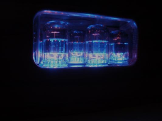
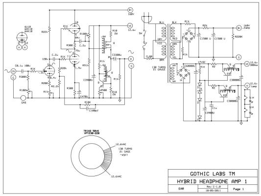
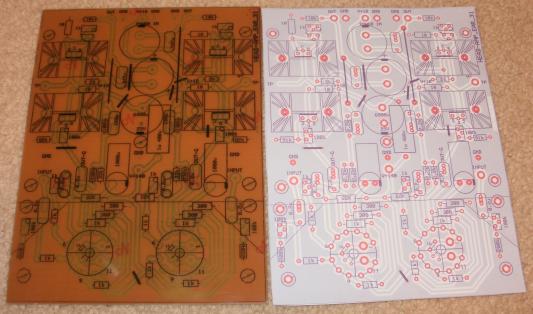
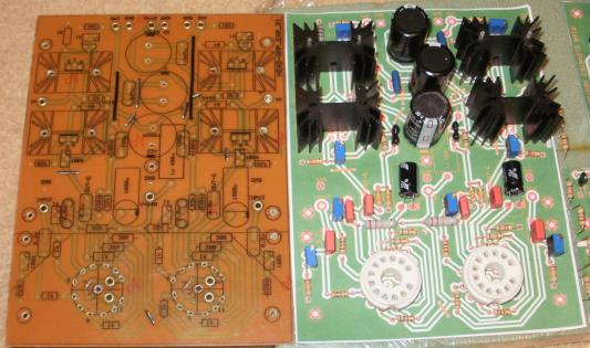
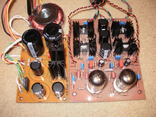
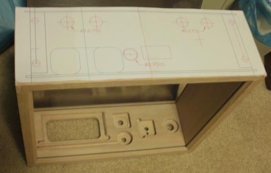
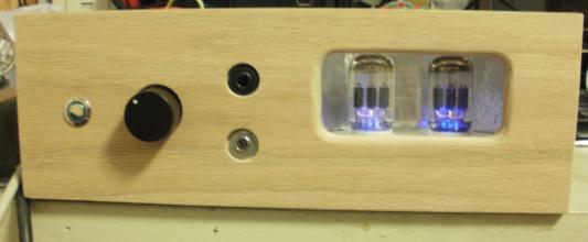
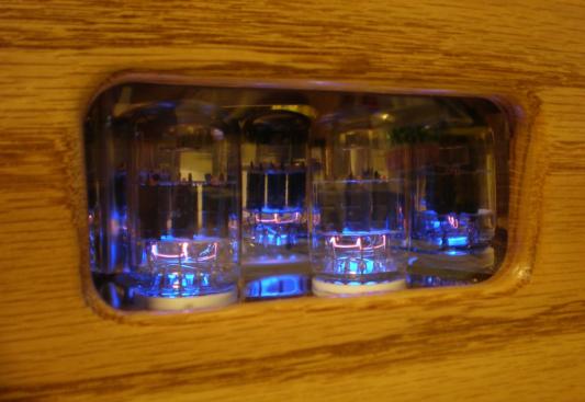
If you were to crank up “ WideSpread Panic”, “RatDog”, “LeadZep” etc…. you might wake them up. You know how kids are, they don’t want to miss any fun.. I researched the forums for the virtues of all tube, all tube transformer-less, all silicone, etc… and decided on a compromise design trying to steal and meld the virtues of each design. I decided on a hybrid design, tube for the first and second stage that would drive a MosFet Class A follower. The MosFet Class A follower has the advantage of higher current output and lower output impedance that allows for compatibility with most headphones’ impedances. Its transfer function approximates a tube, voltage in, current out. To keep it simple and parts count down, I decided on a Compactron triple triode for the vacuum tube section. One of the triodes for the gain stage driving the remaining two tubes as a SRPP configured stage. The SRPP stage can drive the MosFet output stage or allow you to add a tone section if you wish. I designed this as an add-on PCB using gold plated connectors to mount it above the main PCB between the tube and MosFet sections. If the tone section is not wanted, just use a coupling cap instead of the connector pins. The first stage has a cathode pot to adjust the gain for the stage. This will allow you to calibrate the gain of both sides to match. The tone section can be a baxandal section or other as you desire. The last stage is a very simple MosFet Class A follower biased to allow for a symmetrical swing. The compliment to the MosFet is a NPN constant current source (sink) that can be adjusted. At lower output bias levels the outputs just get warm and have enough drive for the higher impedance headsets. With larger heat-sinks and cranked up quiescent current levels, the output stage can drive small speakers. I decided on ½ height heat-sinks and 150mA bias current. The output is cap coupled to the headphones to prevent DC bias. I added .47u Mylar caps across the larger electrolytic. To tame the beast, I added a little GNFB from the output back to the input of the SRPP stage. The power supply was originally 12VAC to the heaters, a filtered 12V to the output section and 160V to the tubes on the PCB. I loved the dynamic range and soundstage, but it left me a little tired after listening. After many hrs of auditioning it, I decided to re-design the power supply. I felt that there was a very low presence of hum. I used a 12Volt AGM battery on the heaters to prove the point. The main change was to add another 12volt filtered section to the power supply PCB and that also required another transformer tap. I used a toriodal transformer for the project for both lower cost and small size for the power available. The wattage of the toriod was ample for the amp’s hunger, so I decided to throw on another set of windings for the heater 12.6 volt DC supply. It took 120 turns of 21gage enameled wire and several layers of clear tape to modify the transformer. The power supply PCB was a redesign that looks more like a capacitor farm. Well bypassed zener referenced Darlington NPNs were used to regulate the 12volt outputs. An advantage of this design was a slow start and ramp-up to prevent the turn-on click noise. The end results of the redesign were well received. With no input, the headphones were quieter than a church mouse and the listening fatigue was gone. On to the chassis build. The chassis is a simple one with a display twist. The head elf decided that the tubes needed to be displayed through the front of the amp. This took a little trial and error routing and fitting of the PCB to the front. The rest of the installation is like the power amps. I added a 304l mirror finish reflector shield to the tubes so at the proper viewing angle it has the illusion of having a small group of tubes in it. It has RCA input jacks in the back and a ¼”phono input in the front to allow for simple MP3 player connection. It also has RCA outputs to drive the power amp that can nest directly on top. The headphones connect to the front with a heavy duty ¼” connector to take potential abuse. I designed this project for the home DIY’er. The information is also posted on the audio forums for non-profit use. For more information and inspiration on tube amplifiers, check out the forums on the net. Check out Parts Express for their parts availability for your next amp project. It is the clarity and soundstage…..
About The Designer
Schooled at DeVry, work experience includes linear design and characterization at National semiconductor, Digital at Intel, Hybrid circuit integration at Cermatek, Analog circuit designs at Honneywell, Space Flight Electronics at TRW/CE.
Keep up the good work , I read few articles on this web site and I conceive that your blog is rattling interesting and holds sets of good info .