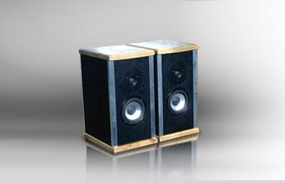
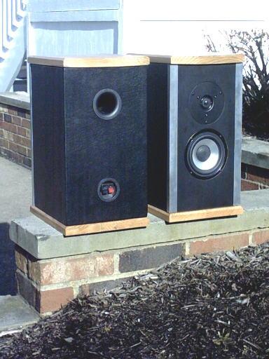
NickA’s Daylum

Designer: Nick Ackerman
Project Time: 8-20 hours
Project Complexity: Professional
Project Cost: $100-$500
Driver Selection
We picked the shielded version of the famous Dayton Silk Dome, this tweeter offers the same performance but in a CRT-safe design. Features a 1-1/8″ silk dome with a ferrofluid cooled voice coil for superior damping. A damped rear chamber lowers the resonance point and provides a very smooth natural sound with excellent on and off axis response. Also we chose the round frame version of our popular paper cone woofer. Features a paper cone, treated cloth dustcap, and rubber surround, all which work together to provide an extremely flat frequency response.
Enclosure Design
The enclosures are tuned to roughly 44 HZ with internal dimensions of (8″L) x (7″W) x (13″H). Internal volume (not including internal brace, drivers, cleats and crossovers) is (0.42 ft3). Internal volume (including internal brace, drivers, cleats and crossovers) is (~0.37 ft3). External dimensions are (9-1/4″L) x (8-1/2″W) x (14″H). The enclosures are built using 3/4″ and 1/2″ thick pieces of MDF. The only places where 1/2″ thick MDF is used is for the tops and bottoms (D) and rear panels (B). (I would have used all 3/4″ MDF but I ran out so I used some 1/2″ that I had laying around in my shop). Before I started cutting with my table saw, I used my circular saw to trim the MDF into smaller more manageable pieces. This was done simply for safety reasons since trying to slide a heavy (4′ x 4′) piece of 3/4″ MDF across your table saw by yourself could be very dangerous. (see picture 1.0) After building several pairs of speakers, I learned the best way to keep all panels the same width/size is to use stop blocks and to NOT move the rip fence until you’re finished cutting out a particular batch of panels. If you are cutting out 4 side panels for example and you suddenly switched to cutting out baffles…..by the time you go back to finish cutting the rest of the side panels, its almost impossible to adjust the rip fence back to its original position you once had. There is nothing more irritating than trying to assemble something where nothing lines up or is not square. (see picture 2.0) Once I cut all the pieces to the correct width, I used the cross cut sled to accurately cut the pieces to length. I clamped a stop block in place to ensure consistent cuts for each piece. Again, the little extra time it takes to set up stop blocks really pays off. Once all of the panels were cut, I used a 3/4″ diameter straight bit on my router table to make all of the (1/4″ deep by roughly 9/16″ wide) rabbeting cuts on the left and right side panels (C). The rabbets only needed to be 1/2″ wide but I made them an additional 1/16 of an inch so there would be an overhang; which would later be trimmed away with a flush trim bit. I like using this method of construction because it helps keep the pieces aligned during assembly, while also providing more glue surface area. (NOTE: For anyone who has never worked with MDF, I highly encourage the use of a dust mask). (see pictures 3.1 – 3.2) Since I would be using the aluminum accent strips (G) on the front, I had to come up with a way to secure/glue the front baffle to the enclosures. I didn’t want to mess around trying to glue the sides of the front baffle to metal so I ended up making small cleats (E) using scrap 3/4″ thick MDF in which the front baffle would be glued to. The cleats provide “baffle-to-wood” glue joints rather than “baffle-to-metal”, which wouldn’t be a good idea. To make things easier on myself, I installed the cleats (E) to the inside of the left and right side panels (C) before I began assembling the enclosures. I made sure to apply a good amount of glue and used a brad gun to tack them in place. I then started assembling the enclosures first by doing a dry fit to make sure things were aligning up properly. (NOTE: I installed the cleats 3/4 of an inch back to account for the thickness of the front baffle). (see pictures 4.1 – 4.2) Once I was happy with how everything fit, I used a good amount of glue (Titebond) and used pipe clamps to hold everything together. To keep the MDF from slipping from the pressure of the clamps, I fired in a few brads with my brad gun. (NOTE: In the picture where it shows the clamps in place, you can see the rear and side panels slightly over hang the top/bottom panels, roughly a 1/16th of an inch. This was purposely done so I could use my flush trim bit to trim off the 1/16″ overhang. My digital camera isn’t exactly the best when it comes to getting close-up shots so I also drew up a quick drawing. I figured it may give someone who is a beginner in woodworking a better understanding of what I trimmed away with the flush mount bit. The end result leaves a very smooth, almost invisible joint.) (see pictures 5.1 – 5.3) Since I only used 1/2″ thick MDF for the rear panels, I decided to add an internal brace (F) to help stiffen things up a bit. The internal brace itself is made out of 3/4″ thick MDF and fits in between the rear panel (B) and the front baffle (A). The internal brace measures (8″L) x (2-1/4″W) x (3/4″H) and has three 1-3/4″ holes drilled all the way through. I used a 1-3/4″ Forstner bit mounted in the drill press to make the cutouts. To make the driver cutouts in the front baffles, I used a circle cutter. It takes a little while because you have to set the speed of your drill press to spin at very low RPM’s and apply small amounts of downward pressure. The end result leaves a near perfect hole. (see pictures 6.1 – 6.2)
Amplifier/Crossover Configuration
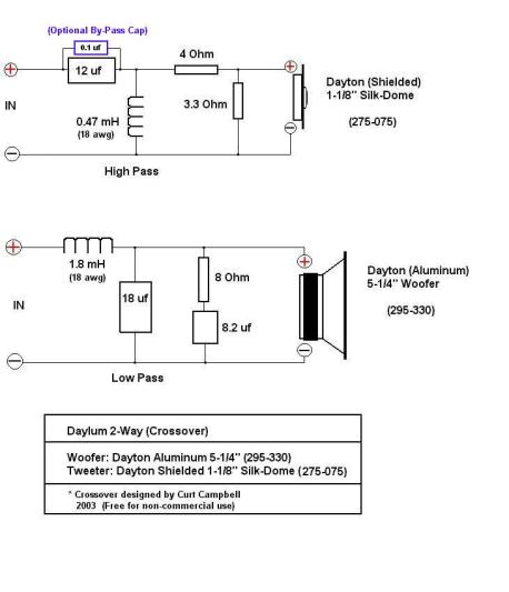
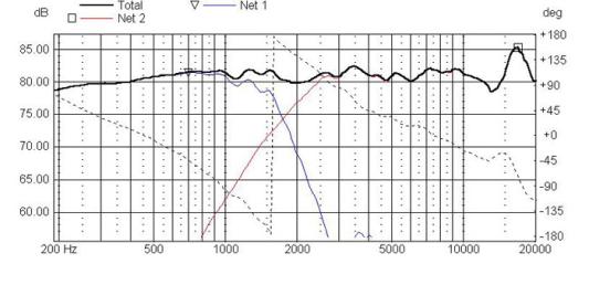
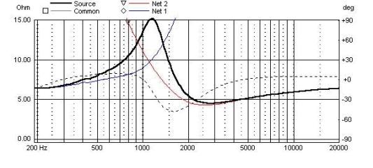
I can’t thank Curt enough for taking the time to design the crossover for this project. He also was kind enough to give me a hand with how to explain some of the “technical” aspects of the crossover while writing this. The tweeter section is a 3rd order Butterworth at 2,100 HZ which uses a 2nd order electrical network. The woofer section is a 6th order Linkwitzriley acoustic slope at 1,700 HZ. This was accomplished by using a 2nd order electrical network and Zobel. (NOTE: Curt mentioned to me that the first woofer break up mode is just visible on the plot at 3,600 HZ and is down -25 db from the summed response.) Baffle Step was included which was modeled at approximately 4 dB with system sensitivity consequently being around 81 dB. Curt also stated that the combination of mixed order slopes and under lap provided good phase tracking through the crossover region. All of the inductors used are 18 gauge air-core Jantzen’s. For all the resistors, I used Dayton “Audio Grade” 10W non-inductives. For the capacitors, I was going to use all Dayton Polypropylene Caps but at the time I went to place my order, Parts Express was temporarily out of stock on a few values so I used a few Solen Polypropylene Caps instead. I only used Dayton Poly Caps in the “low-pass” portion of the crossover, which is an (18uf). Curt also suggested to me, that if I wanted, I could use a bypass capacitor. Using his suggestion, a (0.1uf) Dayton Film-Foil Bypass Cap was used in parallel with the (12uf) Solen Cap in the “high-pass” section. When I was ready to assemble the crossovers, I didn’t have any thin wood laying around so I used a few scrap pieces of 1/2″ MDF to make the crossover boards. Once I soldered all the components together, I gooped on a ton of hot glue to secure everything to the boards. For extra security, I later applied a bead of Liquid Nails to each crossover component just incase the hot glue ever failed. I probably won’t use hot glue anymore since I like the way Liquid Nails works. The crossover schematic shown is a copy I made using Curt’s original layout. I was going to use the schematics he sent me but since they included the (DCR) values for the inductors, I felt this may have confused a few people.
Enclosure Assembly
After I finished making all the cutouts in the front baffles, I covered the front surfaces with black Formica. To apply the Formica, I used contact cement (I used Liquid Nails brand contact cement). MDF is really absorbent so I applied 3 fairly heavy coats of the contact cement (allowing 20-30 minutes before applying each additional coat). I only applied 2 light coats to the Formica. Once joined, the two pieces bond instantly and permanently. (NOTE: I would highly recommend using a “quality” mask when working with contact cement. Even in a double car garage with the door half-way up and using one of those cheapo dust masks, I started to get a headache. Having discussed this issue in the PE forum I learned to use “quality” masks that are designed for dust AND odors.) Next I finished the baffles by using a 3/8″ rabbeting bit equipped with a bearing to flush mount all of the drivers. Once the baffles were finished I set them aside in a safe place and worked on finishing the enclosures. (The baffles are the last pieces I glued in place – here’s a good reason why! At first, I originally cut baffles to accept the Apex Jr. tweeters. As mentioned earlier, I ended up taking Curt’s advice on using the Dayton Shielded Silk-Dome tweeters so new baffles had to be made). I sensed Curt perhaps felt kind of bad that I had to remake new baffles but it really wasn’t no trouble at all. To cut the holes for the (1-1/2″ dia x 4″L) ports (260-402), I used a 1-5/8″ Forstner bit. (NOTE: This particular port from Parts Express requires a 1-5/8″ hole cutout because of the small plastic tabs that stick out.) I also used a Forstner bit to make the holes for the round (press fit) terminals (260-295). Once I drilled everything out, I went over the enclosures with 100 grit sandpaper to remove any imperfections. (see pictures 7.1 – 7.3) On the inside of the enclosures, I applied a bead of Liquid Nails to all of the joints and corners. 1/2″ thick foam was used on the top, left and right sides and to the lower-half of the rear panels. The foam I used was purchased from a local arts and crafts store. (NOTE: no fill was used.) I used black vinyl to cover the sides and rear of the enclosures. The vinyl I used was also purchased from a local arts and crafts store. The only thing I don’t like about this stuff is that I had to use contact cement to make it stick; it was pretty messy. I’ll probably never use this stuff again since Parts Express now sells vinyl which already has an adhesive backing. I used one continuous wrap of the vinyl all the way around (sides and back) and left roughly a 1/2″ over hang on the tops and bottoms. I wasn’t too worried about what the top and bottom panels looked like because I covered them up with 7/8″ thick solid oak panels. To keep the press-fit terminals and ports from ever wanting to fall out, I used more Liquid Nails to secure them permanently. To attach the 3/4″ aluminum channel (G), I simply pounded them on with a rubber mallet. Since they were such a tight fit, I didn’t use any type of screws or glue to help hold them on. To get rid of a few scuffs/scratches in the aluminum accent strips, I used 320 grit sand paper followed by some steal wool. The end result matched the aluminum woofers very well. (see picture 8.0)
Conclusion
My first impression of how they sounded were very good. I was very pleased with the amount of bass the aluminum woofers were putting out. We’re not talking subwoofer bass here by any means but considering only using a 5-1/4″ woofer, it was very well respectable. To help break the drivers in, I set my satellite dish to a channel that plays only music. After letting them play for about 24 hours on the music channel, I actually started to notice slight changes in the sound. The tweeters seemed to have a smoother sound while the bass from the woofers sounded deeper/cleaner. To get a feel for how the speakers reacted to various types of music, I spent a few hours listening to a variety of CD’s. After hours of listening and while I thought the overall sound was great, I still thought the tweeters sounded perhaps just a tad to laid back. I removed the baffles and temporally replaced the 3.3ohm resistor in the L-pad with a 2.7ohm. I then spent a few more hours listening to see if it made a difference and it did. It seemed to give the speakers a completely different sound with things such as symbols and female voices sounding more alive. The end result? I ended up using the 2.7ohm resistor in the L-pad since it made the speakers, in my opinion, sound the best. They seem to work good with all different types of music and provide really good imaging. If anyone wants to build these speakers I would suggest experimenting with a few extra different valued resistors in the L-pad. Listen to the original L-pad setup first for awhile before making a decision to make any tweaks. These aren’t the loudest speakers you will ever hear but I didn’t mind since they were going to be used in a small room and for mainly background sound. This was a fun project to build and I’m more than happy with the way they turned out. The 3/4″ aluminum accent strips really highlight the aluminum woofer cones and since this was such an important part in the design, I decided not to use grills. Thanks First, I wanted to thank Parts Express for providing such excellent customer service. With out the quality products they sell and the “tech talk forum” they provide, I probably would never be in this hobby. Second, I want to thank everyone I talk to in the forum. I greatly appreciate everyone’s opinions, ideas, guidance and comments. And one more time…thanks again Curt for the crossover. Last but not least, I wanted to thank my wife for putting up with this hobby of mine. No matter how many boxes of parts I get from PE…no matter how many times she hears the same song over and over while I do crossover testing…and no matter how many tools are laying on the living room floor….she still somehow smiles.
About The Designer
My name is Nick Ackerman and I live in Canton, OH. I’m 27 years old and happily married to my wonderful wife Debbie. Some of my hobbies include: speaker building, woodworking and car audio. You can find me posting now and then on the PE forum under the name “Nick A.”
Project Parts List
|
Part # |
Description |
Qty |
|
295-330 |
1 |
|
|
275-075 |
1 |
|
|
260-402 |
1 |
|
|
260-295 |
1 |
|
|
081-435 |
1 |
|
|
255-264 |
1 |
|
|
255-228 |
1 |
|
|
027-434 |
1 |
|
|
027-572 |
1 |
|
|
027-564 |
1 |
|
|
027-452 |
1 |
|
|
004-8 |
Dayton Audio DNR-8.0 8 Ohm 10W Precision Audio Grade Resisto |
1 |
|
004-4 |
Dayton Audio DNR-4.0 4 Ohm 10W Precision Audio Grade Resisto |
1 |
|
004-3.3 |
Dayton Audio DNR-3.3 3.3 Ohm 10W Precision Audio Grade Resis |
1 |
|
004-2.7 |
Dayton Audio DNR-2.7 2.7 Ohm 10W Precision Audio Grade Resis |
1 |
+ There are no comments
Add yours