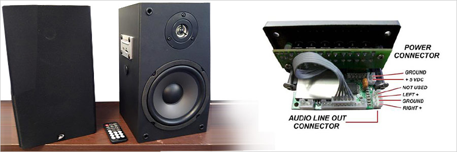
Perfectly Portable B652s
Designer: mikevv
Project Time: 1-8 hours
Project Complexity: Professional
Project Cost: Under $100
How To Make Your Own
Remove the drivers and stuffing. Two pairs of wires (one white and black pair for the woofer, one red and black pair for the tweeter) and a capacitor are attached to the internal cup terminals.
Remove the wires about two inches from the terminals for connection to the DTA-2 left speaker output. A capacitor lead is soldered to the positive terminal. Cut this as close to the terminal as possible and gently remove the capacitor; set aside for future use.
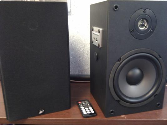
Mark a line on the side of the cabinet where you plan to install the MP3 player module (320-350) and DTA-2’s volume control (300-385). The DC power jack (090- 488), and 3.5 mm stereo input jack (090-317) should be rear mounted, and the easiest place is on the speaker terminal cup. We installed the MP3 module and volume control on the left of the right speaker so that we could use the remote control and adjust volume while sitting at a desk. The power jack and 3.5 mm stereo input jack are mounted on the terminal cup. We cut a 2-1/2″ wide by 1-1/4″ hole for the MP3 module.
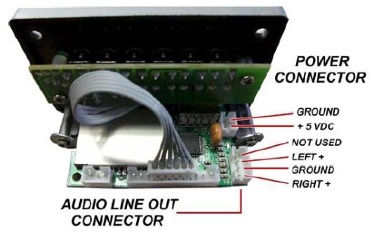
About an inch below the MP3 module, we drilled a 5/16″ through hole and a 1/2″ recess hole for the mounting of the volume control included with the DTA-2. We made our recess hole on the outside of the cabinet (for ease of drilling), pressing the volume control’s mounting nut into place. To make the volume control parallel with the cabinet, washers were used to make the back surface of the volume control level with the metal retaining tab. You could also file the tab down. Connect the ribbon cable that feeds to the DTA-2. Drill the holes for the 3.5 mm audio input and the 2.1 mm power jack, which are 7/32″ and 5/16″ respectively. The speaker terminal cup was used since the thickness facilitated easy mounting. The first part we began wiring was the MP3 module. For all of the connections on the MP3 module, we used 18 AWG speaker wire. Each wire was about 12″ longer than it had to be for performing all work outside of the speaker enclosure. The +5 VDC and ground wires were soldered to the bottom of the MP3 module at the solder points that feed to the pins above. The left and right wires were soldered to the bottom of the board.
The MP3 module was then installed using #8 x 1/2″ self-tapping truss head screws (which are a little on the large side with regards to the hole diameter), was what we had on hand. Substitute with any screw that suits your taste and needs. #6 fits the screwhole diameter properly.
Prior to installing the 3.5 mm jack (centered above the speaker terminals), cut and separate the eight wires within the Belkin Cat5 cable removing them from the cable assembly. These will serve as the conductors for the audio input jack. Cat5 cable conductors were chosen for their flexibility, and feed into the through holes on the 3.5 mm jack perfectly for soldering.
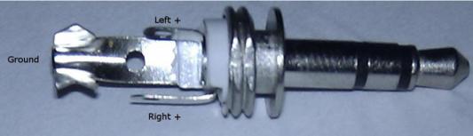
We soldered a solid blue conductor to the center tab of the jack for ground, a white striped wire to the small silver tab for the left positive, and a solid orange on the small gold tab for right positive. Again, 12″ of extra wire was added to each conductor to facilitate ease of future installation and wiring. When connected to a patch cable, the wiring follows the tip (L+), ring (R+), sleeve (ground) convention.
Install the jack into the speaker terminal cup and once you are satisfied with its position (the inner ring abutting the patch plug should be flush with terminal cup) use epoxy to hold it in place. After five minutes we tested the jack to make sure it would stay in place while testing continuity between the opposite end patch plug and the internal wiring.
Next, solder the DC power jack with the 18 AWG Belkin speaker wire observing polarity. With this particular jack, there are two ground tabs; one centered, and one on the right with tabs in the 9, 12, and 3 o’clock position. The left tab is your +12 VDC. Once soldered, be sure to cover your connections using heat shrink.
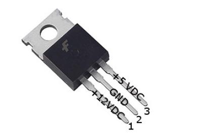
Install the DC power plug into place on the terminal cup, centered and below the speaker terminals. There is an angle to the lower section, so make sure you have your hole drilled as low as the cup allows. Once installed, use a small amount of epoxy to hold it in place. Connect the 12 VDC power supply listed on the parts list and check for proper voltage and polarity. Up to 12.5 VDC is perfectly fine when not under load. The MP3 module requires 5 VDC power, and if you would like to use the USB port for charging a smart phone (in addition to reading MP3 files) it is highly recommended to use a voltage regulator in conjunction with the 12 VDC power supply. We chose a 7805 IC for the voltage regulator due to the wide operating input voltage.
The three pins on the 7805 are (from the left): 1 for voltage (+) in, 2 for shared ground (-), and 3 for voltage (+) out. Feed the +12 wire from the 2.1 mm DC input jack to pin 1 of the 7805.
Additionally, cut a section of positive conductor from the speaker cable to create the +12 for the DTA-2 power input. Strip 3/8″ from the end of the wire from the jack and 3/8″ from each end of the second positive conductor. Solder the two separate cables together and place about and 1-1/2″ piece of heatshrink over the pair. Solder this pair to pin 1. Solder the +5 VDC wire from the 7805 IC to the +5 VDC on the MP3 module (make sure you place a piece of heatshrink over one of the wires). Do this also with one of the ground wires from the 7805 to the ground wire of the MP3 module.
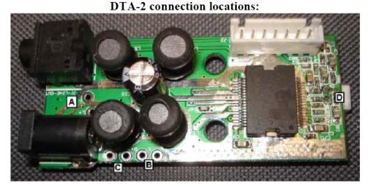
At this time you can mount the voltage regulator onto a small copper covered coin (drill a hole through this coin; it is to be used as a heatsink) and secure inside the speaker cabinet using a 4-40 pan head screw no more than 1/2″ long. The second +12 VDC wire from the 7805 and second ground wire still need to be connected to the DTA-2. DTA-2 connection locations: (A) Left speaker output (B) Right speaker output (C) Power input (D) Not used First, solder a pair of speaker wires onto the + and – terminals for A; repeat for B. Separate red and black wires are included with the DTA-2 kit. Use these for the power connection at C. Ferrite cores are included with the kit, as well as two non-polarized capacitors. Loop each pair of speaker wires coming from the DTA-2 through and around its ferrite core and set to the side.
Slide a piece of heatshrink over, connect, and solder together the +12 VDC and ground wires, from both the 7805 and DTA-2, together; heatshrink the joints for insulation. Next cover (with heatshrink), connect, and solder together the right speaker output negative (from the DTA-2) to both of the black terminated speaker wires that were removed from the speaker terminals at the beginning of the project, and one lead of the output capacitor. Cover (with heatshrink), connect, and solder together the positive right speaker output (from the DTA-2), white terminated speaker wire (for the woofer), a lead from the capacitor removed from the terminal cup, and the other lead of the output capacitor included with the DTA-2. Cover (with heatshrink) and solder together the other lead of the capacitor from the terminal cup to the red terminated speaker wire (for the tweeter).
Solder the left DTA-2 speaker outputs to the internal speaker terminals, red to the left for positive and black to the right for negative. The output capacitor is then soldered in parallel between these terminals. Connect the ribbon cable from the volume control to the DTA-2, and locate a free, non interfering location within the cabinet to epoxy or hot glue the DTA-2 board to. Epoxy and position the DTA-2 in place.
We now need to feed the audio signal connections from both the 3.5 mm jack and MP3 module to the DTA-2. Due to the number of connections, we found it easiest to solder the audio signal connections together (left + to left +…etc.) and then to a 3.5 mm stereo plug. Once you have this internal patch cable is finished, connect it to the DTA-2 and epoxy (or hot glue) into place. Connect the left slave speaker terminals to the master speaker’s speaker terminals.
Connect the 12 VDC power supply to the 2.1 DC jack. Right away, the green LED on the MP3 module should illuminate. Save a few MP3 files into the root directory of a USB memory stick or SD card.
Connect the storage device to the MP3 module, the module should find the MP3 files and start to play automatically; the green LED will flash when playing songs. If not, press the USB/SD button on the module, then play. Once you have a flashing LED, turn the amplifier on with the volume control and adjust to a reasonable level.
While playing an MP3 file, connect an external audio device to the 3.5 mm stereo input. As soon as a signal is seen over this connection, the amplifier should auto switch to external signal. Remove the external device from the 3.5 mm stereo input. The amplifier will switch back to the MP3 player automatically.
Congratulations, you’re finished!
About The Designer
Most people know me as Mike V, one of the many moderators on the Tech Talk Message Board. I’ve been a customer of Parts Express since I was 16 and have worked here at Parts Express since 2004. I tinker with anything that has an electrical circuit, to include: cell phones, computers, speakers, and cars.
Project Parts List
|
Part # |
Description |
Qty |
|
300-652 |
1 |
|
|
300-385 |
1 |
|
|
320-350 |
1 |
|
|
7805 |
1 |
|
|
129-077 |
1 |
|
|
090-488 |
1 |
|
|
090-317 |
1 |
|
|
109-040 |
1 |
|
|
090-316 |
1 |
|
|
109-352 |
1 |
|
|
081-460 |
1 |
|
|
080-720 |
1 |
+ There are no comments
Add yours