Shia LaBoom


Designer:
Paul Graves
Project Category:
Portable Speakers
Project Level:
Intermediate
Project Time:
8-20 Hours
Project Cost:
$100 – $500
Project Description:
A portable Bluetooth speaker design, sized for a small shelf and intended to give full range sound at good volume wherever it goes.
Design Goals:
This build was conceived to create a portable speaker that could be transported and used on battery power with good bass performance and output. The size and weight needed to be reasonable, and fit on a shelf when at home. The goal was to use full range drivers to keep the crossover simple and baffle size down, and be robust enough to hand off to a pre-teen for their use.
Driver Selection:
Driver selection was facilitated by having a pair of Dayton ND105-PR passive radiators on hand, won from a drawing at MWAF 2018. The goal was to use these radiators in the design, paired up with a full range driver that is capable of pumping those little passives and produce solid bass response.
Starting from an appropriately sized and popular existing design the Sprite by Paul Carmody, the Dayton ND90-4 was chosen for the drivers. These will compromise a bit on the high frequency extension, since a 3” driver simply can’t respond up to 20kHz without very narrow dispersion, but the low frequency capabilities are excellent.
Using Bass Box Pro and the Dayton published specifications for the ND90 and ND105 radiators, the 0.127 cubic foot box plan tunes to just above 60Hz and aligns pretty closely to the Sprite design. Bass Box doesn’t offer a way to easily add weight and tune the PR in simulation, but as long as the initial tuning is high, you can always add weight and lower the frequency. Additionally, a quick calculation of the surface area * Xmax of the radiators indicates that they will be just above the double air movement capability recommended for passive radiators.
As this is intended to be a self-powered system, these drivers will be paired with the Dayton KAB250 Bluetooth amplifier board and be coupled with Dayton’s matching battery board and I/O accessories. The KAB250 was chosen due to the better Bluetooth standard, even though the full 50W per channel is overkill for the project.
Enclosure Design:
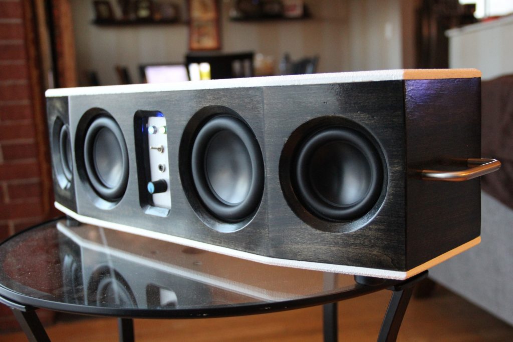
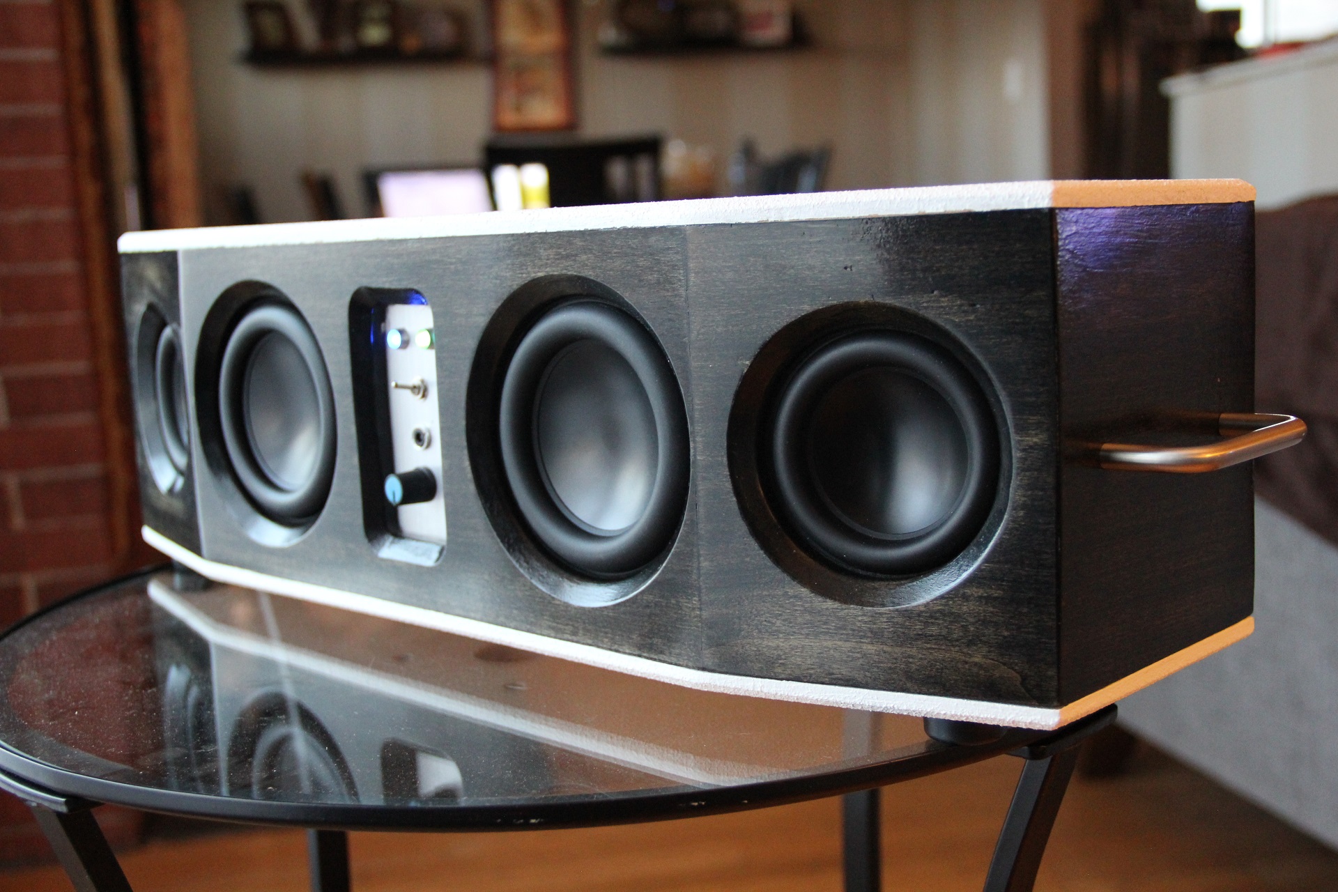
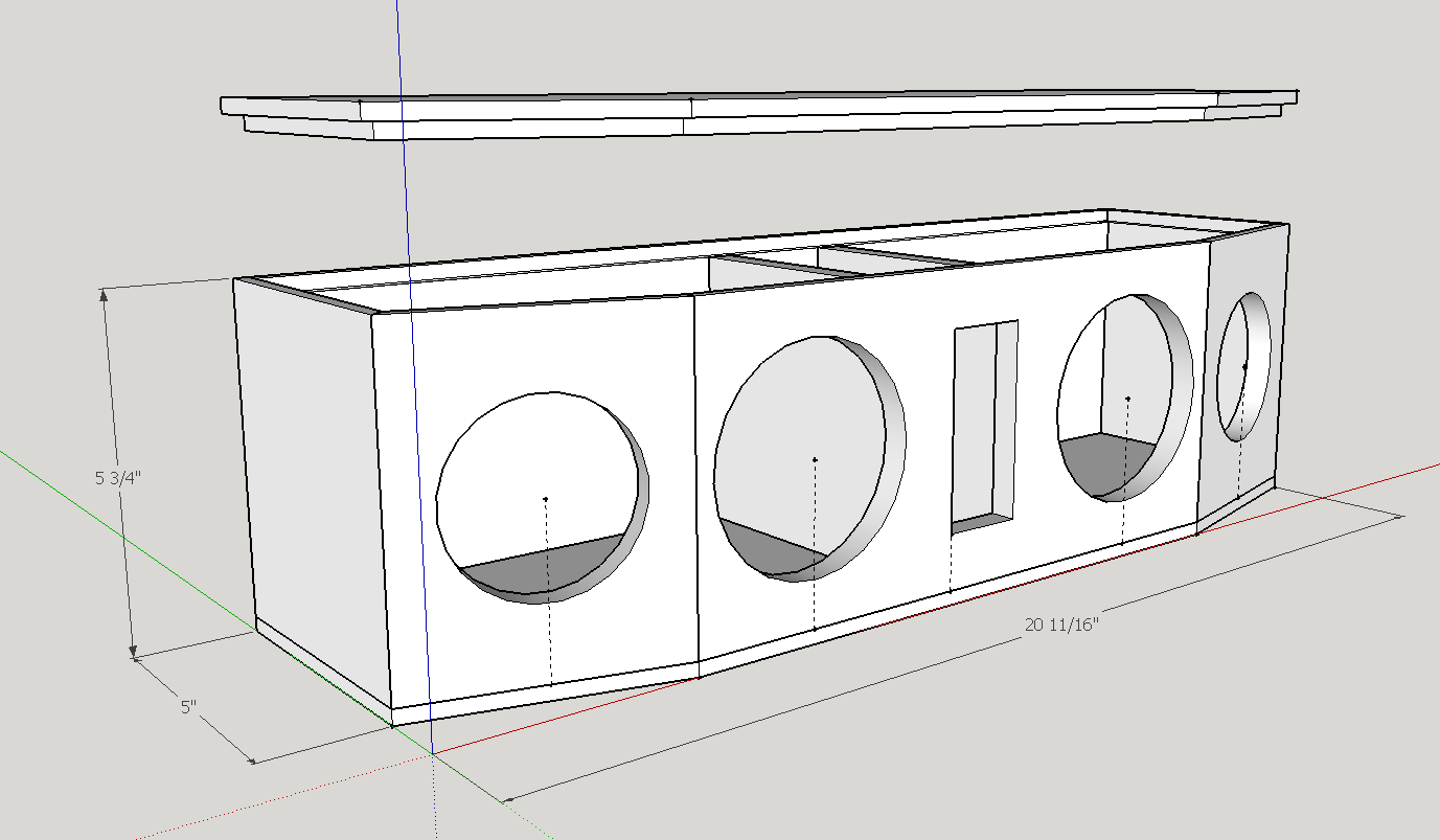
The enclosure was conceived with all 4 cones facing front, an isolated chamber with the electronics in the center and small panels on the front and back for controls and connectors. I wanted to angle the main drivers out slightly to help disperse the high frequencies a little wider in the room.
In order to facilitate easier assembly, the height of the cabinet was selected to match available board sizes from the local hardware. A standard ½” x 6” plank measuring 5.5” wide would be used for the front and sides, with ½” stock MDF for the top and bottom.
The angle for the drivers was arbitrary, and selected at 15 degrees. A SketchUp model was made to plan the board cuts, which will be done using a compound miter saw. The top and bottom panels will be inset using a ¼” rabbet to make the whole assembly 6” tall.
The enclosure will be glued together for all sides and the top, with a removable bottom panel to allow future access to the drivers and electronics.
Enclosure Assembly:
Wood in hand, the first step is to create the outside frame of the box using the solid poplar boards. I verified the miter cuts with a small angle gauge, making the 7.5 degree, 37.5 degree, and 45 degree cuts at the dimensions planned in SketchUp.
Once cut, a rough test was done with some painter’s tape to make sure the cut angles were good. These panels would need to be cut up for the driver holes and panels prior to glue up. The whole frame would need to be glued and solid prior to cutting the top and bottom panels. The panel cuts were drawn out on the boards, and a frame was made out of hardwood for a flush trim router bit to follow. The hardwood was simply stuck on using carpet tape to make the cut.
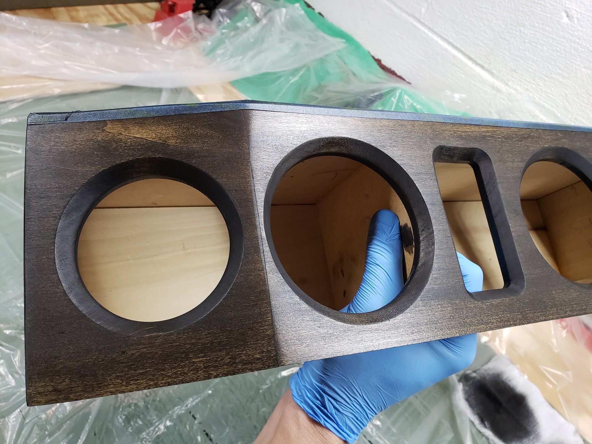
By drilling a hole first, the router was able to make the rest of the cuts. The driver holes were cut using a Jasper circle jig set to size. After all holes were cut, the router was setup as a table with a 45 degree chamfer bit to add finish to the holes.
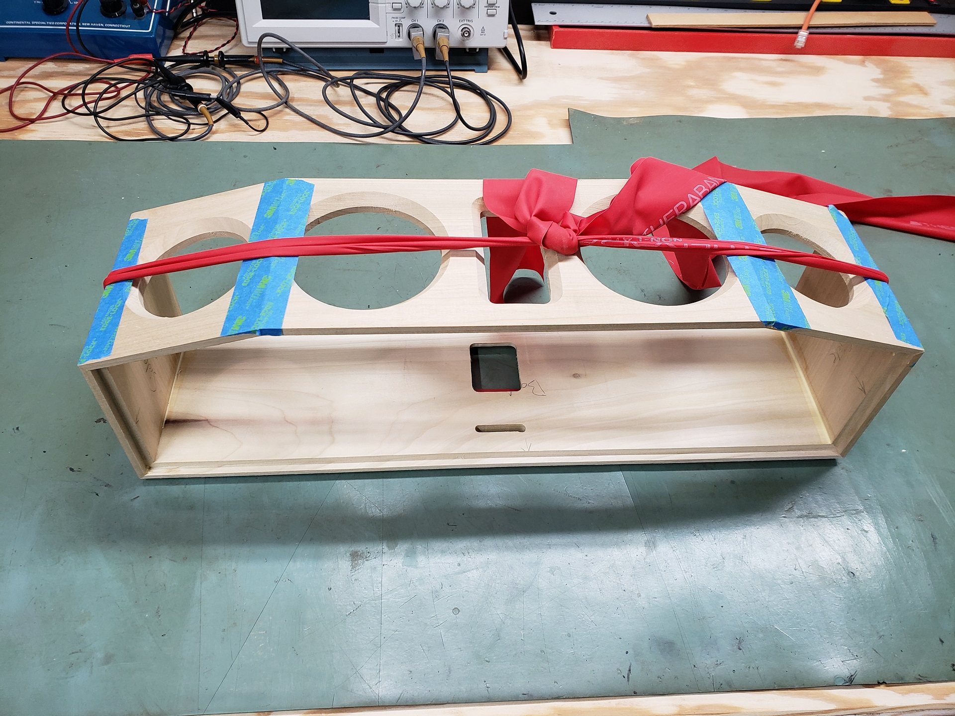
The top and bottom edges were then hit with a multi bearing rabbet bit set to ¼” depth. Then the frame was prepped and glued using the corner tape method with a resistance band for tension.
Once the glue was completely dry, the frame was sanded and filled where required to prepare for the top and bottom to be created. The MDF was cut just a bit larger than the frame, then clamped to the frame for the flush trim bit to cut to match. The clamp method requires the whole trim to be done in 2 passes. One side was trimmed then taped to the frame to keep it steady, then flipped and re-clamed to pass the other side. Once the top and bottom panels were trimmed to size, the ¼” rabbet bit came back out to match the frame and inset the panels.
The inside dividers were simply cut with the miter saw and fit tested. The top was then glued on and sanded flush. Rather than using the chamfer bit, the edges were angled slightly using a hand plane and sanding block.
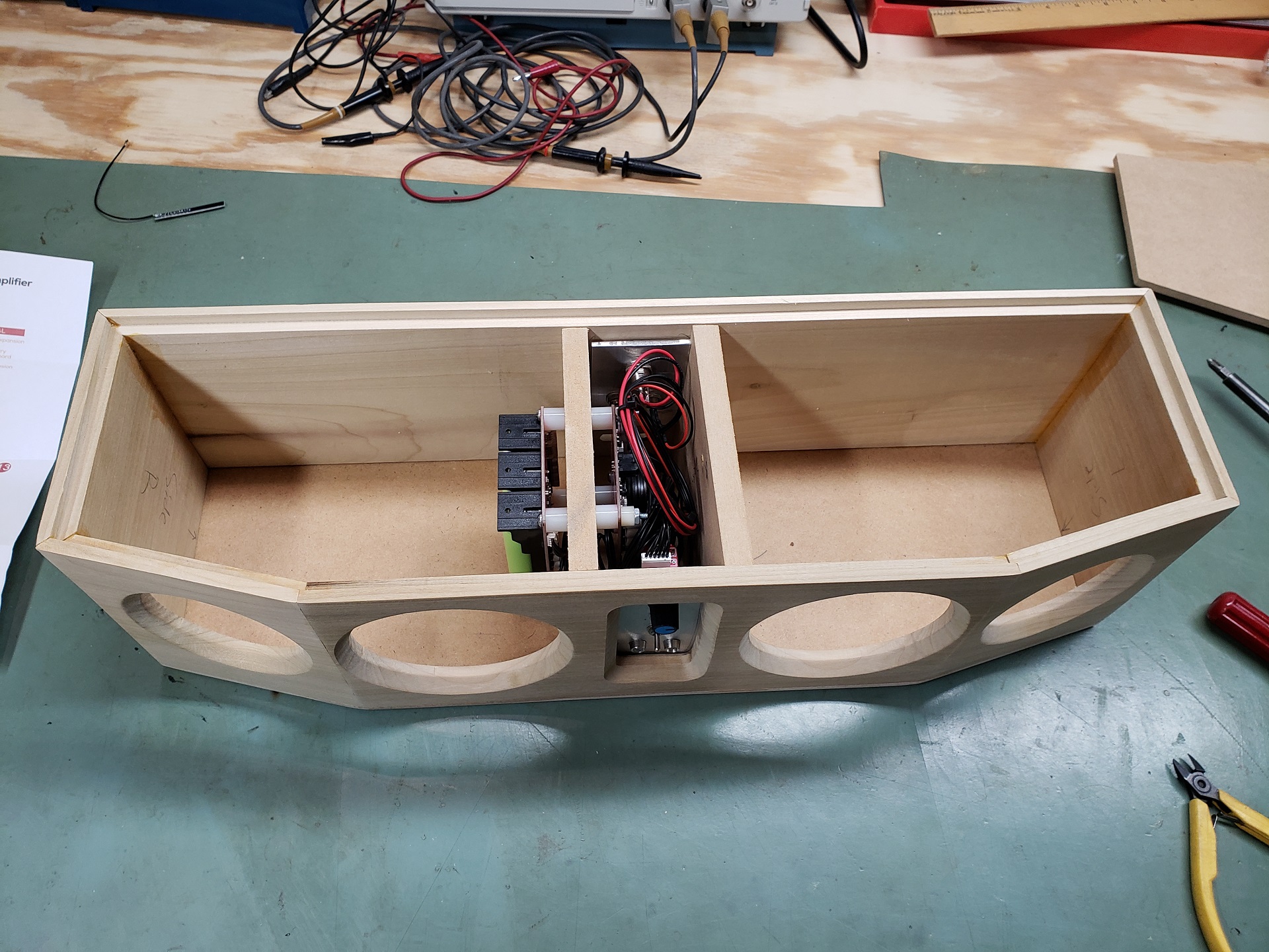
At this point, the electronics were prepped up and the panels created from 2”wide aluminum stock. The dimensions turned out to be tighter than planned to fit the KAB boards together in the center chamber, so some improvising was needed. I opted to place the battery board into one of the speaker chambers and leave just the amplifier in the center chamber. This simplified mounting since I could use one set of bolts with standoffs on either side for the boards.
The cabling for the battery board was passed through by removing the pins from the connector and carefully re-inserting to the correct positions. The speaker cables were passed through to the back panel to allow easy testing. All holes in the dividers were sealed with hot glue. I then prepped the baffle boards by pre-threading the #6 screws in to mount the drivers. The limited space necessitated using some creative screwdriver techniques.
To mount the bottom panel, #8 threaded inserts were needed. The ¼” rabbet surface is too small, so a small section of the poplar was cut to add to the sides. This made plenty of surface to do the inserts. Since the middle divider panels were hand fit and not perfectly square, I calipered the dimension to hit the center of the ½” MDF.
The second divider wasn’t installed yet so the finish could be completed. The solid poplar will be stained dark and contrasted with a white Duratex finish on the top and bottom MDF panels.
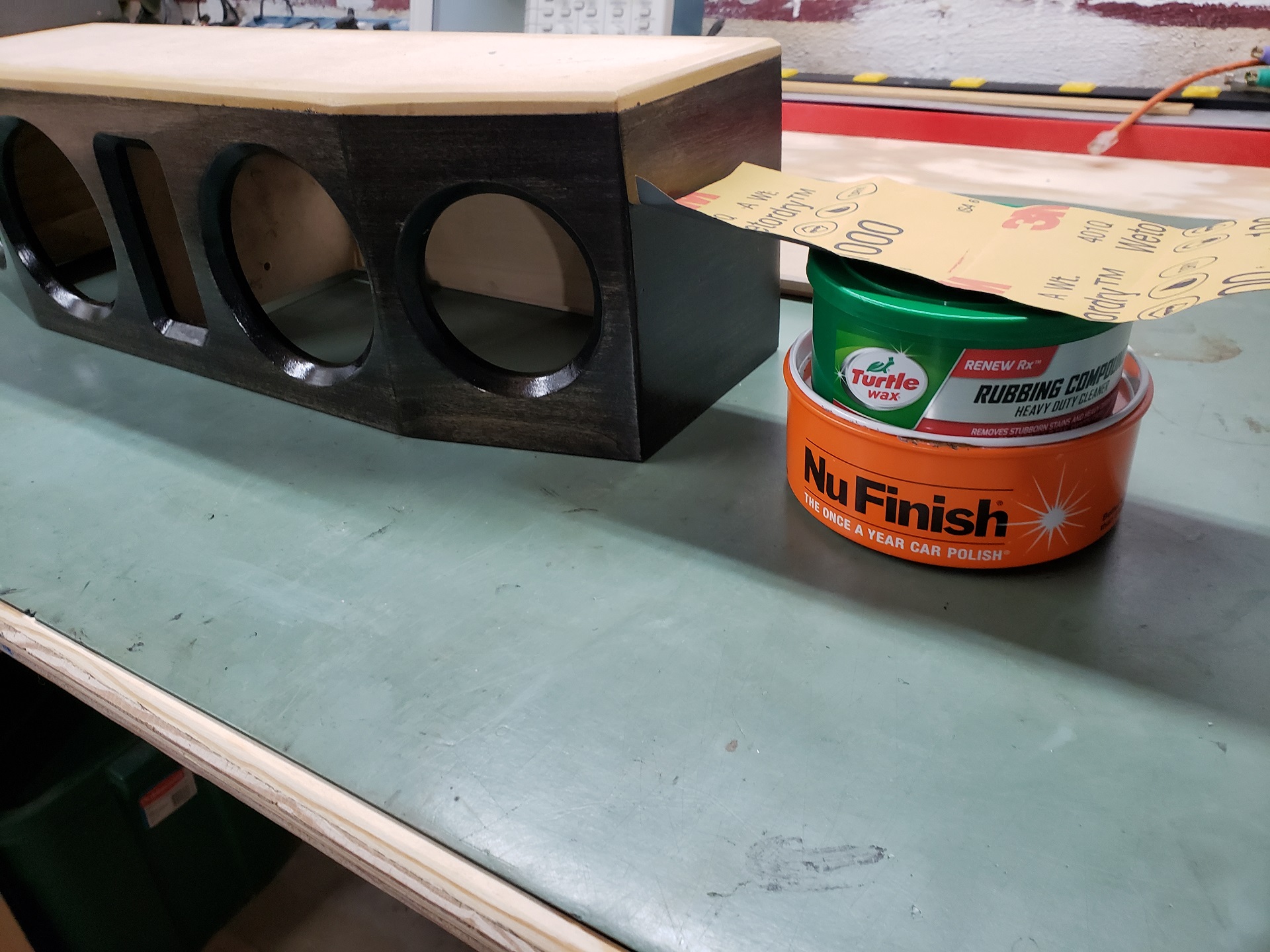
Several applications of Minwax ebony stain later, it was time to poly coat. The small surfaces to apply the poly and angles made it a little tough to get a smooth finish, so after 3 coats a little bit of processing that would have eventually led to a piano gloss finish was applied. The poly was wet sanded with 1000 grit, then rubbing compound, then polished. I didn’t wet sand to full flatness, just enough to smooth it out and avoid sanding all the way through the poly.
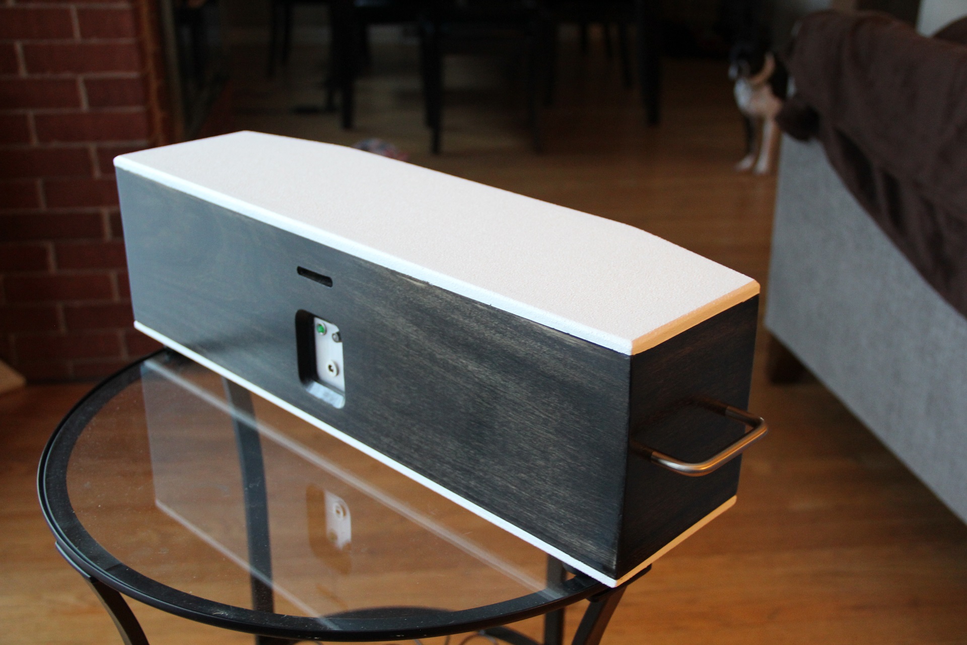
This left the box complete enough to install all electronics and test for the filter design. After acoustic measurements were taken, the top was taped off and the bottom finished with the white duratex. Once ready, the bottom panel was gasketed with weather stripping to seal all the chambers. Extra thickness was used for the dividers, which ended up slightly short and are critical to keep the individual speaker chambers sealed.
For good measure, I added a bit of soft touch denim insulation to the back panel after completion. This likely has very little effect, but can reduce the higher frequency reflections from the back wall making it back to the cones.
Crossover Design:
While full range drivers don’t need a “crossover”, a filter is needed to help adjust the frequency response for the loss of bass due to baffle step, and the high frequency loss due to the diameter of the driver. This is typically called a contour filter. As always, the best way to design the filter is to use the response and impedance data from the actual speaker.
The impedance data was captured using DATS, which gave me the files to use for the filter design, and verified the tuning of the PRs.
As measured, the tuning frequency of the PRs ended up quite a bit lower than modeled at around and just under 50Hz. This is due to parameter differences in the ND90 and / or the ND105 parts in real life vs. the specification sheet. I removed the thumb nuts from the PRs to make them as light as possible to raise the tuning as high as it could be, but ultimately this design could use higher tuning. These will work as is though, and result in an extended bass shelf (EBS) alignment for the tuning which will produce better low bass, but at a reduced level.
The acoustic measurements were made with a calibrated mic and ARTA. The signal was passed by Bluetooth from the PC to the internal amp exactly as it is intended to use, so the measurement is exactly as it will be in normal use. The downside was that both R and L sides were powered for the measurements, resulting in some interference from the drivers depending on mic position. Acoustic cancellations and reinforcements will happen at the mic due to the distance between drivers and the wavelength of the sound in the air.
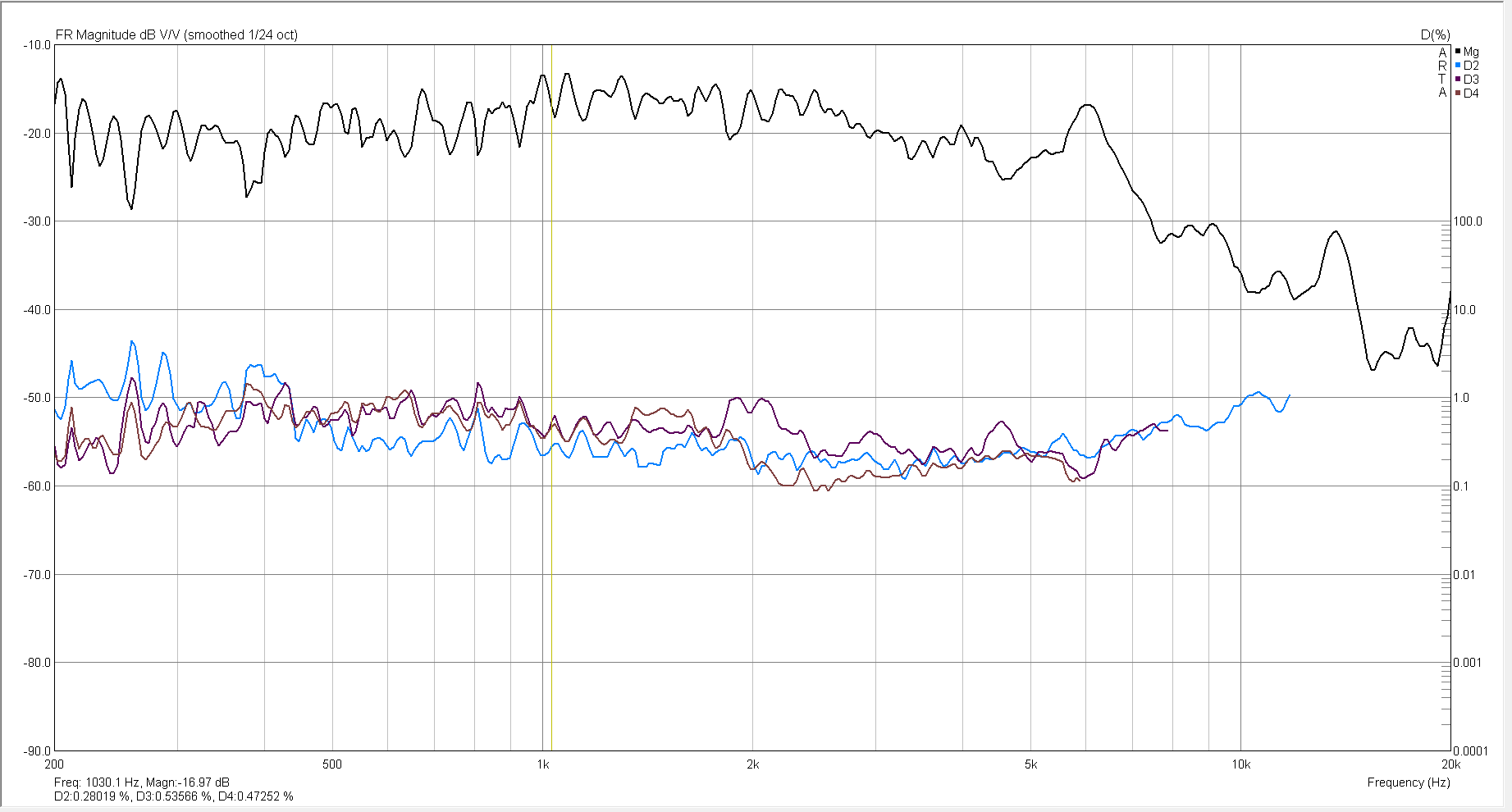
I made a measurement dead on the front at 24” distance, making the drivers both 15 degrees off axis. This shows the beaming of the 3” drivers and their resulting drop in high frequency response. Using that measurement I checked the distortion of the system at approximately 85dB output.
Distortion wasn’t too bad, running about 1% across the spectrum. For the filter design, I used an on axis measurement of the R side speaker. This was pulled into Xsim to apply a RLC notch filter, creating a bit of a smiley face EQ curve to the driver.
The filter was adjusted until the high end and low end were about on par. The filter ends up being a 6dB drop centered at around 2.5kHz.
With only 3 parts, these were point to point soldered and screwed into the cabinet. A liberal blob of hot glue was added to help secure the hefty inductors. I went with more expensive 14ga inductors to keep resistance low and as much power as possible going to the speaker.
Tips & Tricks:
Working on little enclosures is a pain, plan your assembly steps carefully! For a re-do of this project I would increase the width or depth a bit to allow the amp and battery boards to live in the center compartment as intended. I’d also be sure to pre-thread the driver mounts before assembly, add the side handles before the drivers are installed, and other little things that just ended up making a little more work.
Staining poplar is a bit tricky, for a more even result consider using a conditioner.
The pairing of the ND90 with the ND105 PRs is just a bit off, the system would sound a bit punchier if the tuning ended up a bit higher.
Conclusion:
Very pleased! This speaker has been passed on to my daughter for jamming pop music, and has been happily received.
Overall sound is a party, strong bass and full sound. The high frequency response is definitely lacking a bit, and this could use a pair of tweeters to brighten it up. As is though, it is still quite enjoyable and in any situation where a portable system is needed, this does the trick. I’m looking forward to bringing this along on road trips and having a proper speaker for movies and music.
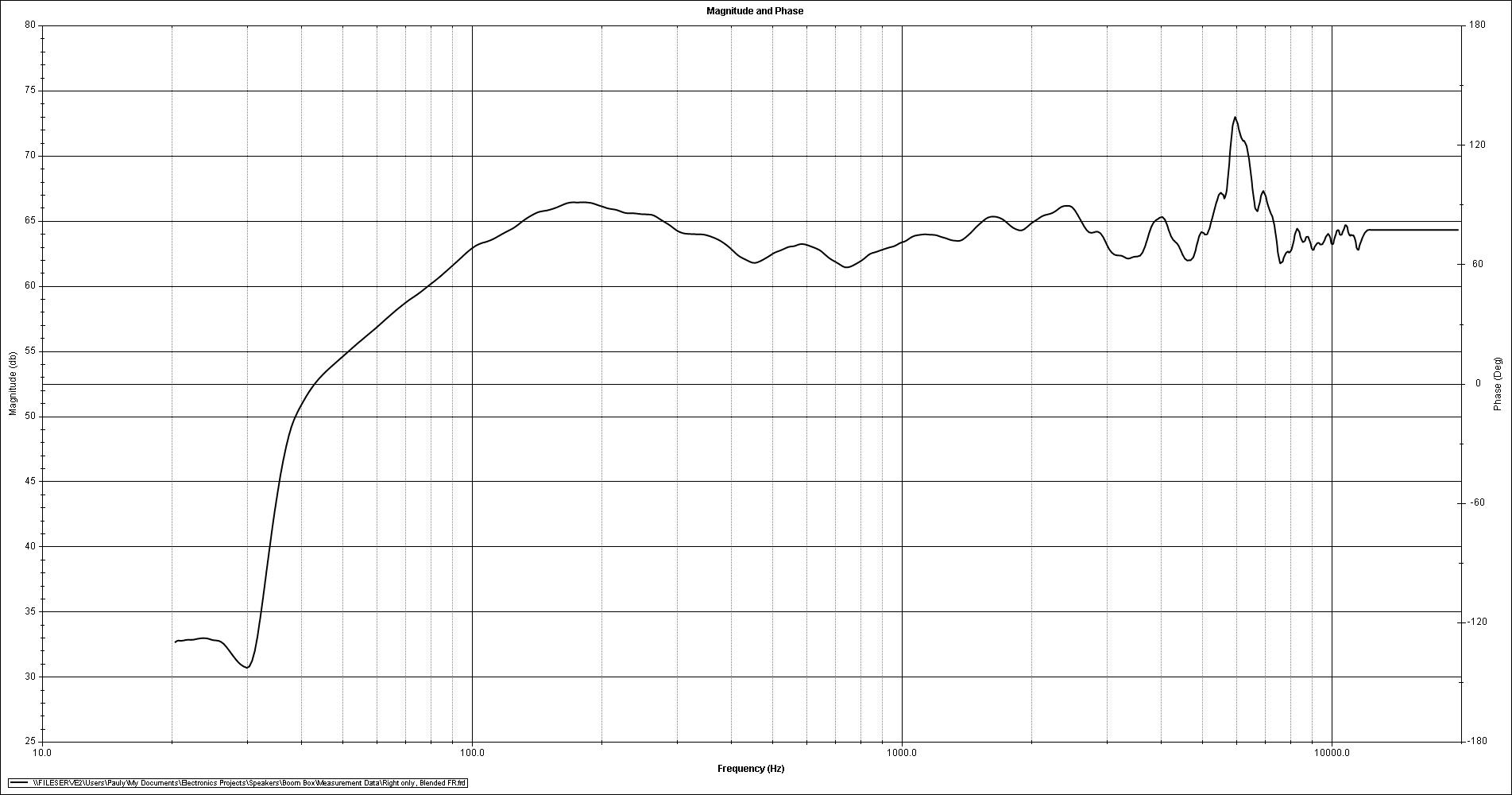
The completed speaker was measured quasi-anechoic to confirm the full system frequency response and the effectiveness of the contour filter. Measurement was made a 1 meter on axis with the right side speaker driven by the internal amp only. Close mic measurements for both the driver and passive radiator were adjusted, summed, and blended with the far field.
The resulting frequency response is meets +-3dB from 80Hz to 15kHz, with the exception of a 6kHz and 12kHz peak due to the breakup of the aluminum cone in the ND90-4. The bass response is deceptive, the low tuning of the passive radiators allows the system to continue to output clean bass all the way below 40Hz where the system is down approximately 10dB.
About the Designer:
Paul Graves (aka Wogg) is an electronics engineer and has been designing and building speakers since he was a teenager.
Project Parts List:
Poplar will stain OK, just do not sand above 120G and use gel type stain.
I was under the impression that this speaker has a battery power design. What component or part number includes the battery mount? What kind of battery (lithium I assume) and size (AA, AAA, etc.)?
Missed the battery board in the parts list… I used the KAB-BE at matches the Dayton 18650 cells are sold separately.
Seems the author has made some presumptions: “tune the PR in simulation”… What is “PR”… is it port response? If no what is it?
I think it’s a awesome design and great build. I had a similar design a few years back but minus the passive radiators.
Is there a wiring diagram? I just bought the components and am making something similar. Intention is to be able to put in golf cart.
Can you explain how u wired the coil, capacitor and resistors. I am new.