Synergy Horn


Designer:
John H
Project Category:
Freestyle Speakers
Project Level:
Advanced
Project Time:
20+ Hours
Project Cost:
$100 – $500
Project Description:
This project makes a Multiple Entry Horn (MEH) similar to a Synergy Horn. The horn design is for full range home audio use. Efficiency is about 86 dB at 2.83 V rms.
Design Goals:
The design goal was to make a compact MEH that would be comparable with high quality home audio speakers. The design goal meant that only a single midrange driver was required to meet home volume levels, the woofers needed to perform in the 30Hz range in a small enclosure, and the tweeter needed to perform better than a compression driver used in many horn designs.
Driver Selection:
After testing some tweeters in the horn model, the Tymphany XT25TG30-04 1″ Dual Ring Radiator Tweeter was chosen. The horn gain allowed the tweeter to be crossed with lower than expected distortion.
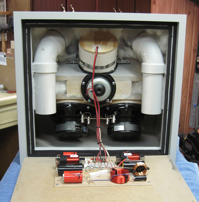
The horn simulations called for a midrange that would work well from 400 Hz to 1,500 Hz. The SPL requirement needed to be above 87 dB at 2.83 V rms for flexibility in the crossover design. The GRS 4FR-8 Full-Range 4-1/2″ speaker was chosen because it met the SPL requirements and could be mounted on its face without the surround hitting the cabinet while playing. The GRS also fit inside a 4 -inch diameter PVC pipe making for a simple midrange enclosure.
The woofers are a pair of Dayton Audio DCS165-4 6-1/2″ Classic Subwoofers. They perform well in a smaller volume and have reasonable sensitivity.
Enclosure Design:
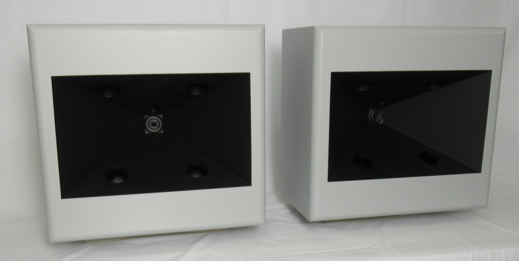
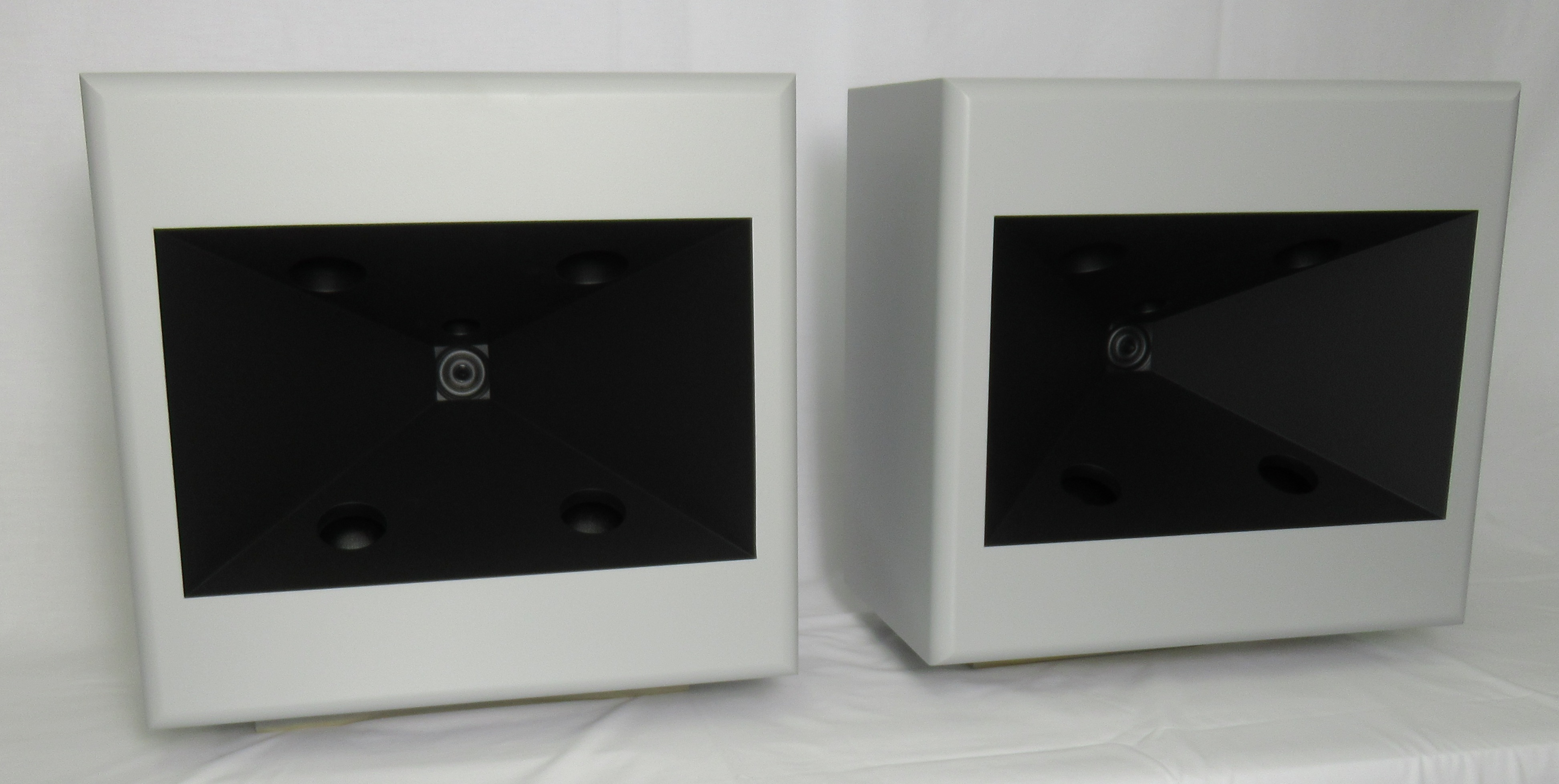
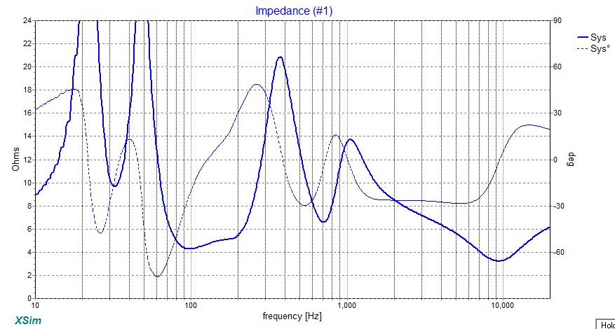
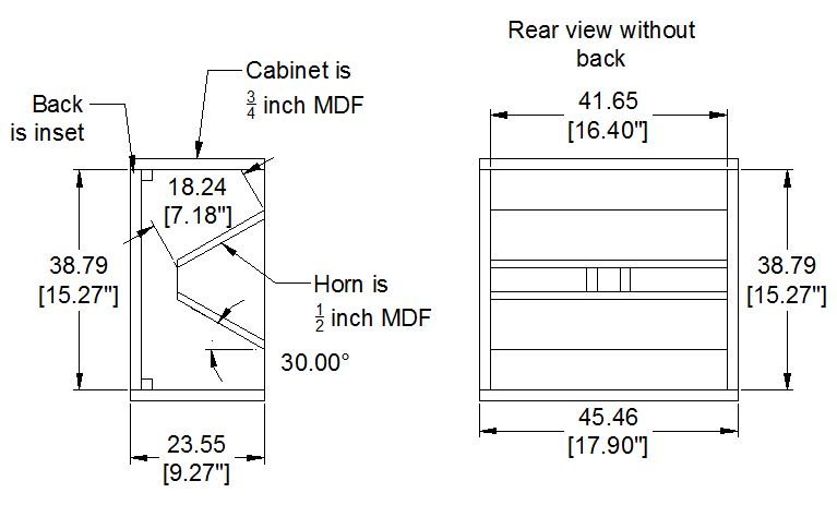
The enclosure design is a stand mount cabinet with a 60 x 90-degree conical horn. The horn is about 6.7 inches deep. The horn is designed to maintain pattern control to 400 Hz. The internal cabinet volume is 20 liters for the woofers. The box tuning is at 38 Hz with an F3 of 36 Hz.
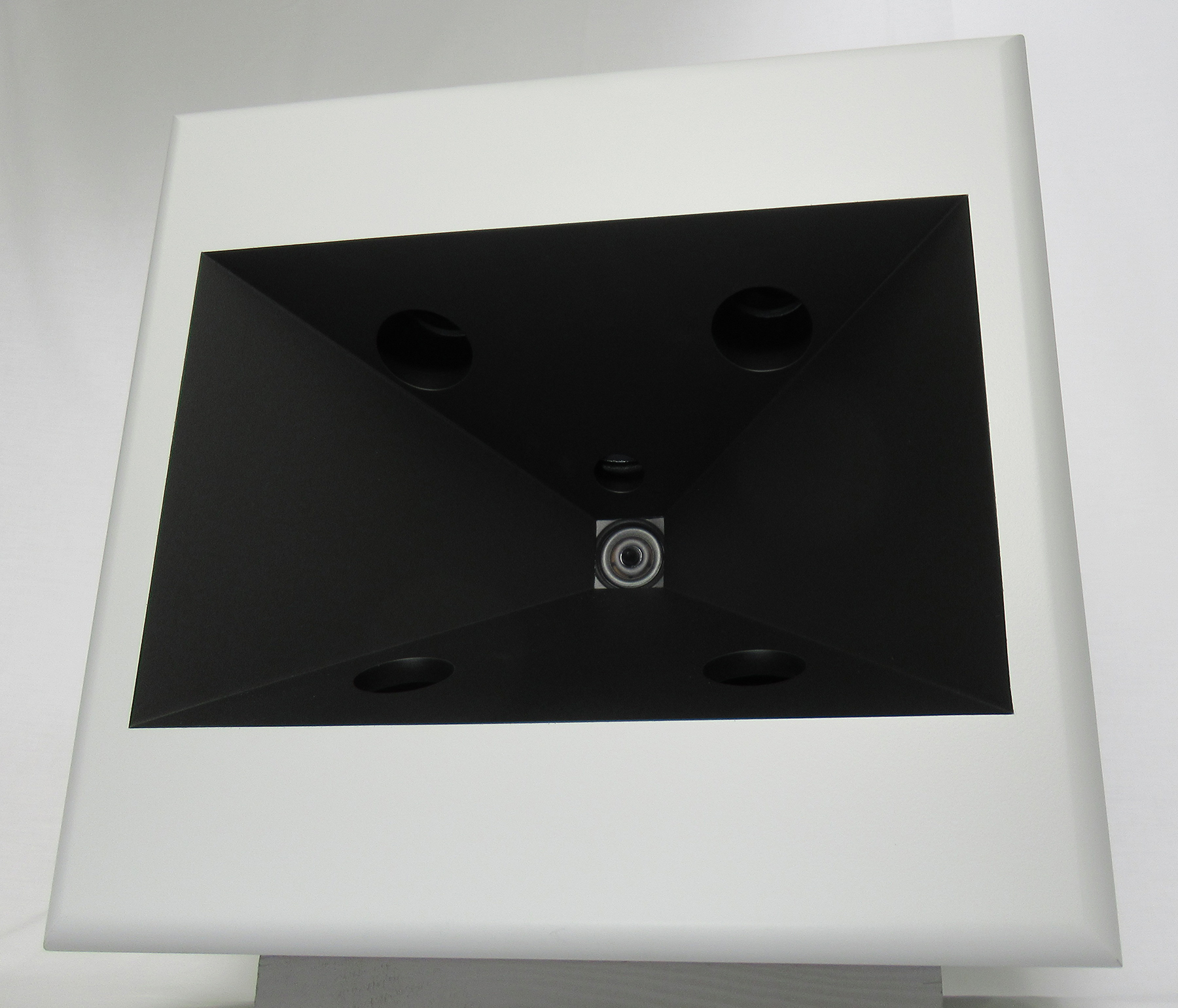
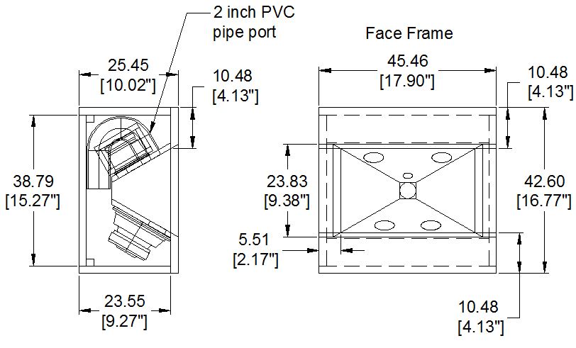
The enclosure is designed for all the drivers and ports to be within the horn mouth. It was found that a square opening for the tweeter performed just as well as a round transition opening.
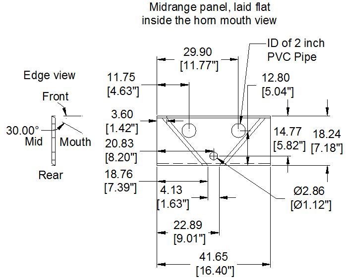
There are chamber resonances associated with the midrange and woofer driver openings into the horn mouth. To simplify the construction the driver openings size and locations were adjusted such that only straight holes are required in the ½ inch MDF.
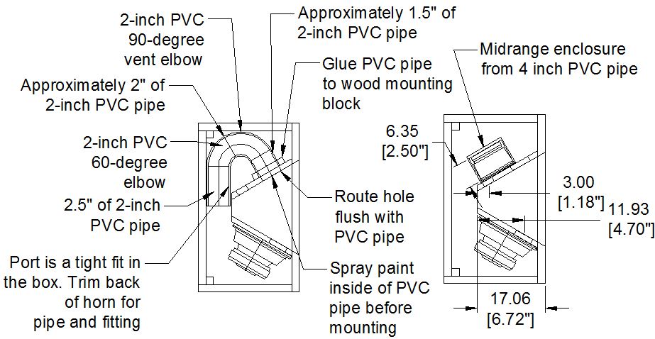
The woofer ports are made from 2-inch PVC pipe.
Enclosure Assembly:
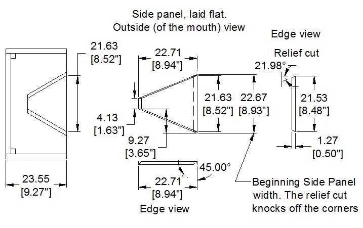
The enclosure assembly is straight forward except for creating the side panels for the horn. The drawings include a plan for jigs to cut out the side panels. Note that the side panels are all the same and 4 are needed.
The enclosure consists of four parts; the rectangular cabinet, midrange enclosure, the horn, and the face frame.
Start by assembling the midrange enclosures. Cut 2.5 inch lengths of PVC pipe and glue to the back of the GRS drivers. Test fit the midrange enclosure, angle mounting brackets and the port PVC mounting blocks on the top horn panel. Assemble the horn. Assemble the face frame. Assemble the cabinet and port.
Final Assembly consists of Installing woofers and midrange. Use a drop of wood glue on the threads to hold the nuts in place. Cut the tweeter flange to center the tweeter in the opening. Add foam gasket to the tweeter opening and mount the tweeter. Install about 1/3 lb. of Acousta-Stuf insulation in the upper half of the cabinet.
Crossover Design:
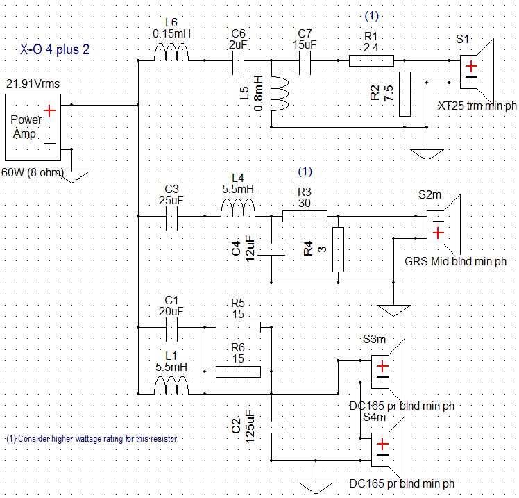
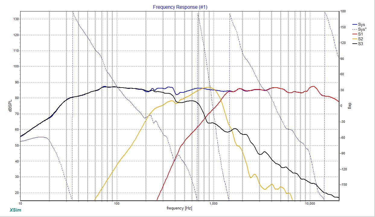
The crossover was designed for flat frequency response with a minimum number of components. The crossover points were determined as a result of the high frequency roll off of the midrange and woofer performance in the horn. The tweeter to mid crossover is at 1,300 Hz. The mid to woofer crossover is at 400 Hz. The slopes are Linkwitz Riley 4th order. In the woofer circuit two 15 ohm resistors are wired in parallel for increased power handling.
Tips & Tricks:
Play with the speaker toe-in to get the imaging correct
Conclusion:
At first it seemed like a lot of work for minimal benefit. Now I’m sold on the inherent clarity of the Synergy MEH horn. The clarity is likely because of the lower midrange distortion or the controlled directivity in the room.
About the Designer:
John is a member of the Parts Express design team
Project Parts List:
Really cool build! I’ve been curious to try a horn build, so I’m going to study this for inspiration.
Awesome build! One of the best i’ve seen. Can you please expand further on the results/sound of the system?
There’s a detailed build log here
http://techtalk.parts-express.com/forum/tech-talk-forum/1331723-synergy-horn-build
What is the nut tool used for?
The nut tool is used to tighten the bolts to the studs holding the mid range and woofers. There was no room to get my hand and a wrench behind the woofers. In the link above, post #76, the PDF files shows not installing studs in some locations as the are inaccessible.
Thanks John for the explanation. I’m going to take the plunge and make a pair for myself using different drivers. I appreciate all the documentation and will use your experience as guidelines for my design. Gar
Awesome build. Great detail. Would love to see an actual synergy horn with 4 mids and one tweeter. Can’t afford Danleys,,but would love to try and build a front stage of synergys. Always wanted to try a micro synergy just for the heck of it.
Awesome looking build. Multiple Entry Horn is quite the name because these look anything but “meh”. 😀
Great looking (and probably sounding) horns, I have couple questions:
What is the power handling on these, (RMS), or don’t you know?
Are the ripples in the response a function of the horn?..driver? ..combination?
Do you think using different drivers would have solved any of it?
Again, congrats on an awesome build! ; ^ }
Thanks
Power handing is based on excursion of the woofers, about 70 watts continuous, 108 dB. The ripples in the response are a function of mostly the shape of the horn, cabinet, and ports, but the tweeter has an affect above 10K.
Great looking buid. One question. As I can see you are only using one midrange driver. Most synergys I have seen are either using 2 or 4 midranges which means that they will fill the horn “symetrical” with sound. With symetrical I mean the midrange opening ports resulting into the horn are on the left/right and uper/down side of the horn the same. Does it have any disadvantage if doing this asymetric (when using only one driver will result that opening is only on one side and not on the opposite)? Is the dispersion pattern upside then differnt to the downside pattern?