The Scimitar’s


Designer:
Dan Neubecker (dlneubec)
Project Category:
Tower Speakers
Project Level:
Advanced
Project Time:
20+ Hours
Project Cost:
Over $1,000
Project Description:
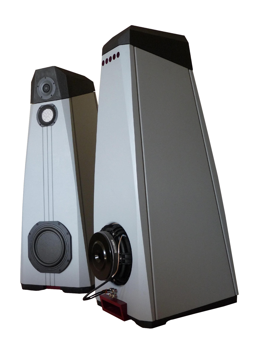
The Scimitar’s are a state of the art, floor standing, passive 3-way speaker utilizing all top end drivers from Tang Band.
Design Goals:
Reference standard performance, including excellent balance top to bottom, flat power response, great off axis performance, low end flat to 20hz in room, with a wide, deep soundstage, capable of high spl with low distortion, all in a unique, attractive, but not too large aesthetic package. To combine some of the best drivers Tang Band has to offer in one speaker. A speaker that would not require additional subwoofers for HT. The use of drivers that could not be easily damaged if left uncovered.
Driver Selection:
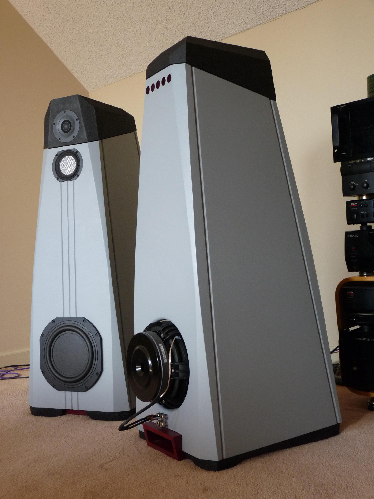
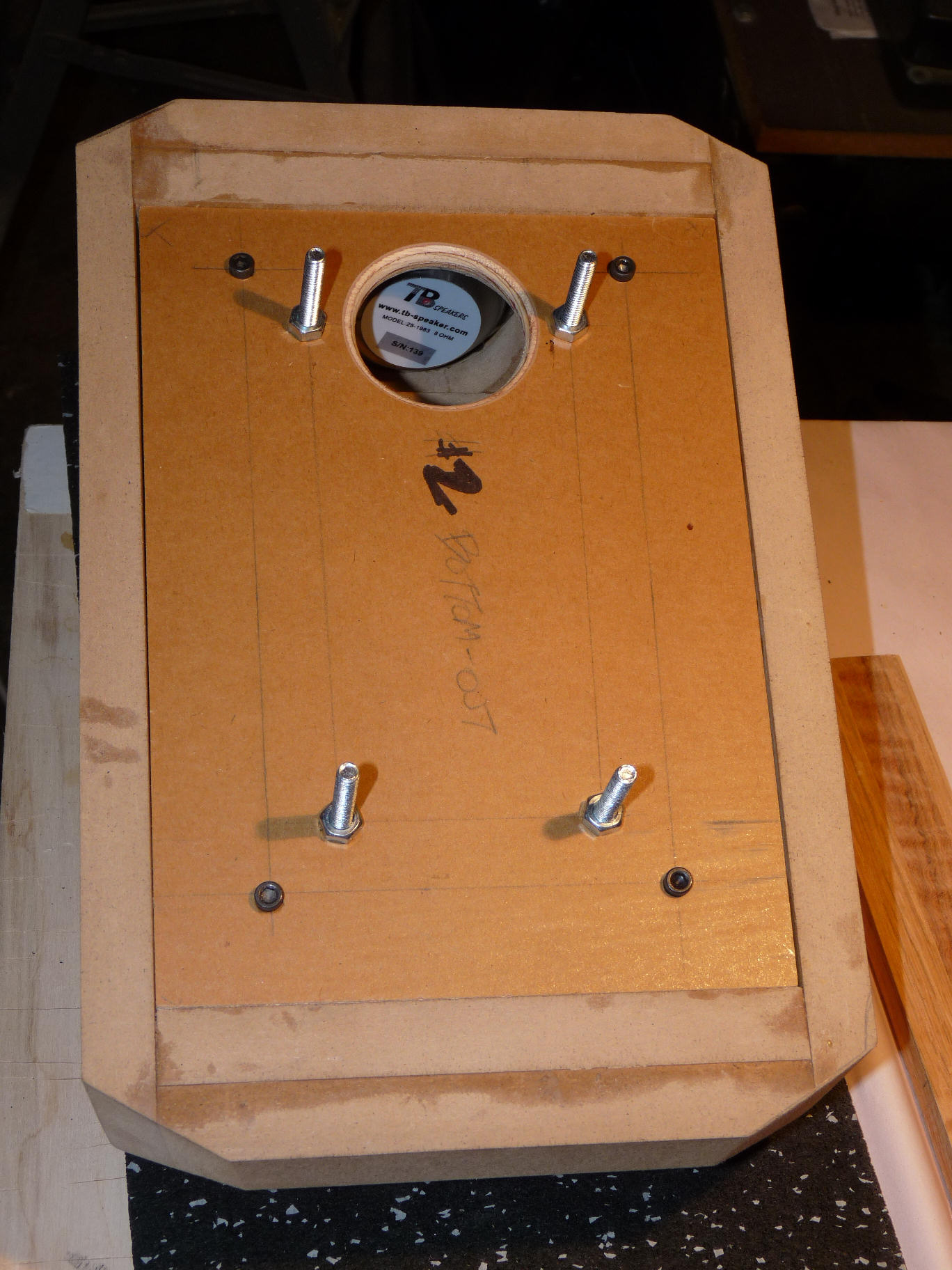
Subwoofer/Woofer: Dual, Tang Band W8-2022 8 ohm subwoofers, wired parallel, and implemented in a push-pull configuration, front and back. This RBM subwoofer is a very low distortion, flat cone subwoofer that has dual surrounds and cone surfaces, with an excellent frequency response all the way to around 1500Hz.
Midrange: Tang Band W4-1757SB 4” Aluminum Sandwich flat cone driver. This neodymium driver has an aluminum honeycomb sandwich construction, with a built in protective cover and boasts extremely wide off axis response. Measurements on and off axis sum to flat all the way out to about 8kHz. These drivers have a very detailed presentation.
Tweeter: Tang Band 25-193 1” Titanium Dome. This neodymium tweeter has a coated inverted dome and is also capable of extremely wide dispersion. Frequency response is only down about 4 decibels at 60º off axis at 10kHz, which is pretty amazing for any tweeter, much less a 1”. It is also a high sensitivity tweeter with an aluminum mesh cover for protection. A shorting ring in the gap results in low distortion.
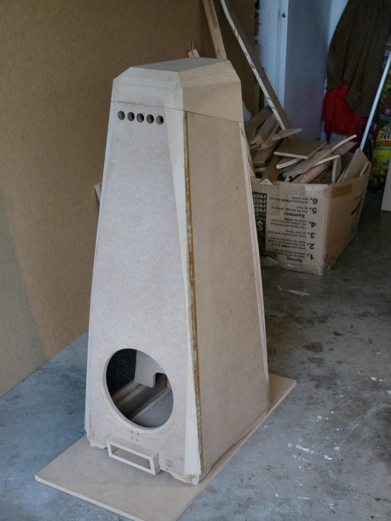
Enclosure Design:
Considerable time and thought was invested in the enclosure design. All sides are tapered and non-parallel, which is intended to contribute to reduced standing waves, decreased diffraction and a non-box-like look. This made it very complex to design in cad as well as to construct. There are around 56 separate parts included in the entire box.
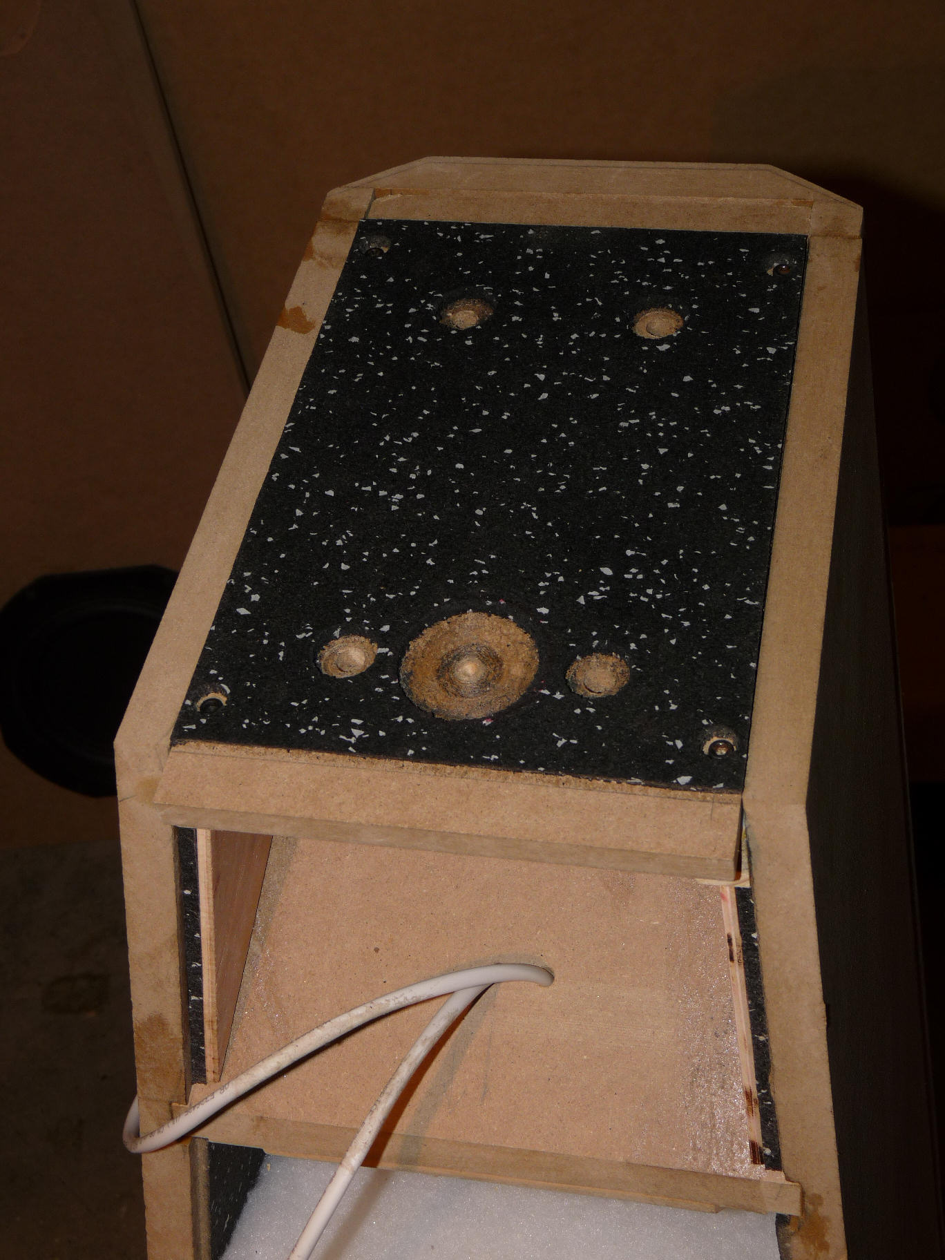
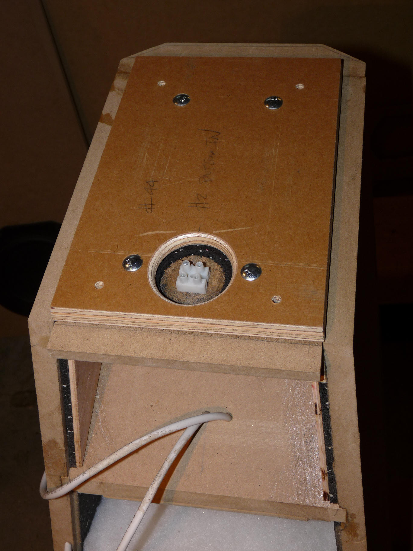
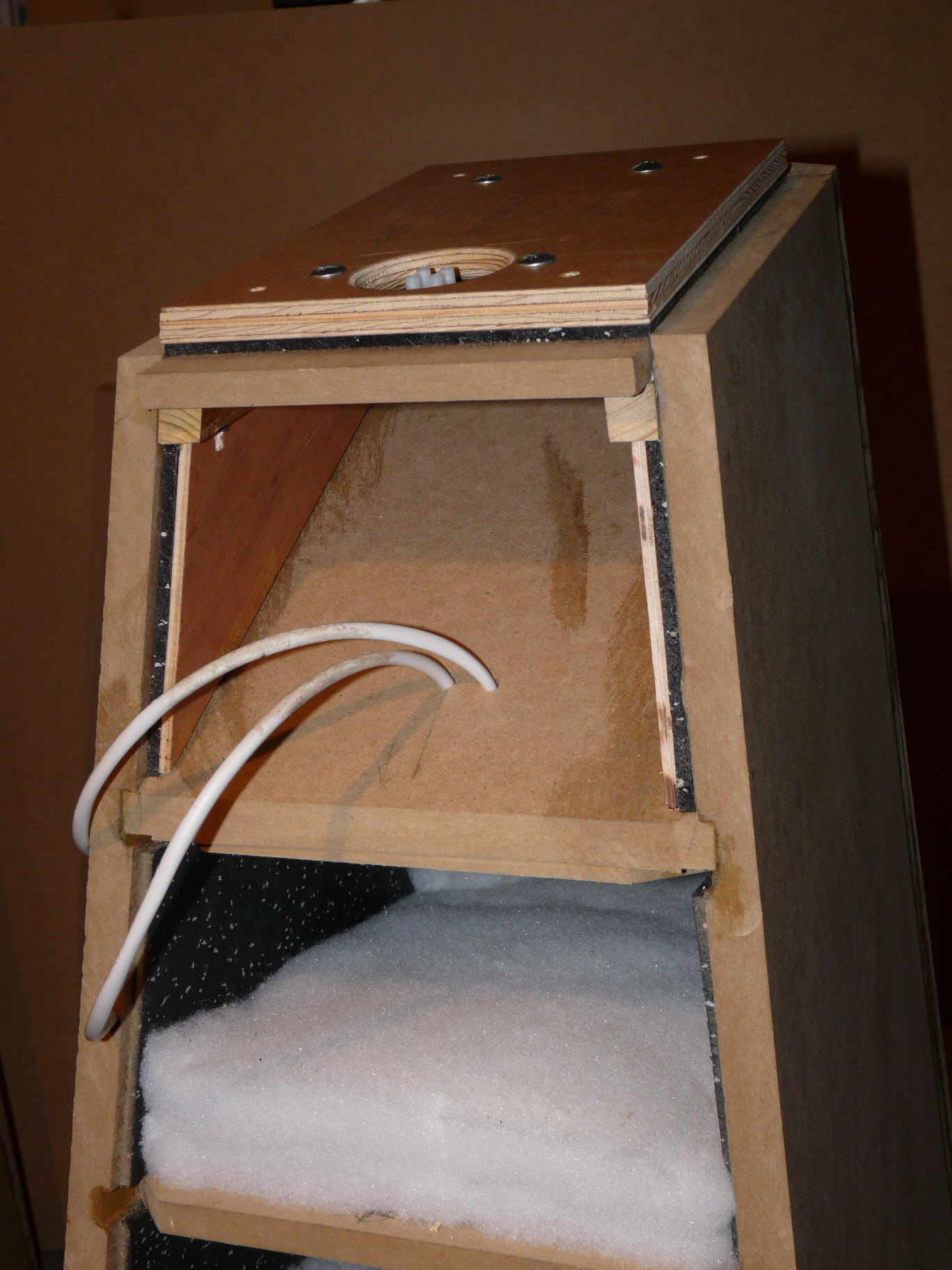
Subwoofer/woofer enclosure: A removable bottom panel was configured to allow access the woofer and mid crossover, plus to install or remove the inward facing rear subwoofer. The subwoofer box is approximately 80 liters and includes a rear facing slot port of 8.06 sq.in, 16” in length, with a predicted tuning of about 20.7Hz and an F3 0f 19.8Hz. In room measured response is flat to at least 20hz. The box sides are ¾” mdf reinforced with additional ¾” pieces and window-type bracing. In addition, 3/16” rubber flooring is glued to the interior sides of unsupported panels to further deaden enclosure walls. A single horizontal layer of 3.5” Ultratouch denim insulation is placed central to the enclosure, above the first window brace. Window bracing is made from ½” plywood and dado’d into the box sides.
The base was designed to hide the spikes used and to make it look like the speaker just barely touches a typical carpet, while still providing a stabilized base for the speaker.
The push-pull subwoofer configuration is said to reduce lower order distortion, though whether 2nd order or 3rd order seems up for debate, depending on who you are talking to.
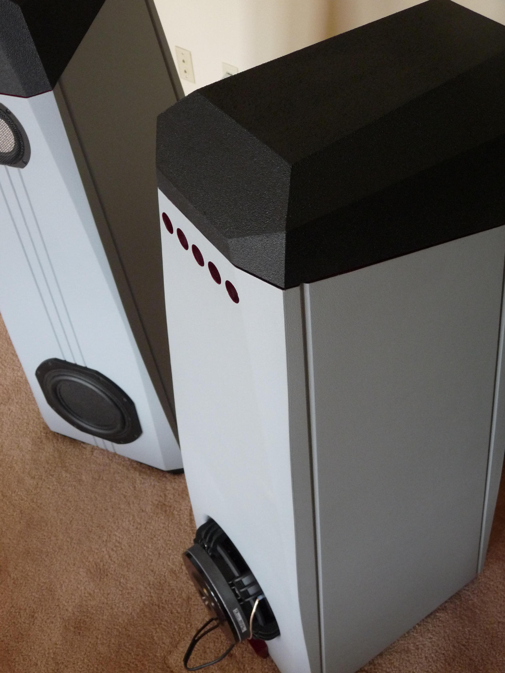
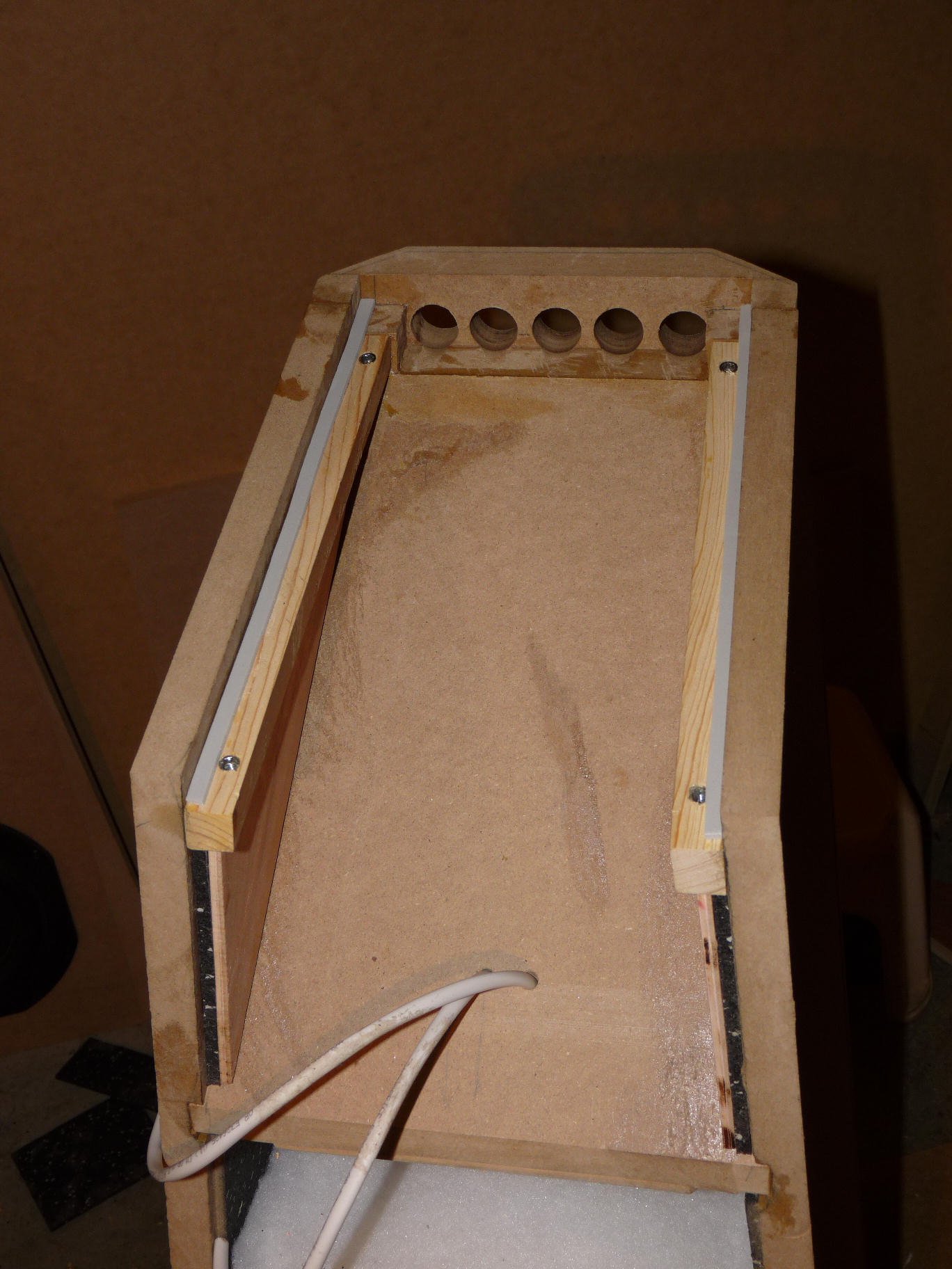
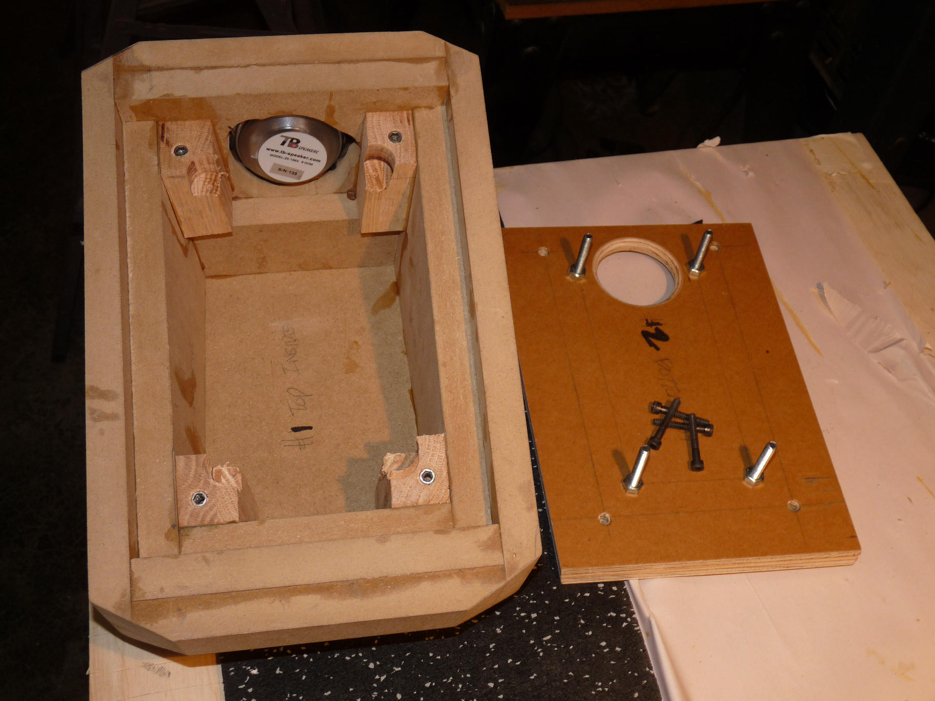
Midrange enclosure: This enclosure has all tapered sides, tapering from front to rear where it is about 1” tall. There are five 1” diameter holes on the rear side. The box is heavily stuffed with a graduated and varied stuffing mix that includes a sandwich of Ultratouch insulation behind the driver, followed by a layer of 3” fiberglass insulation, followed by a thick layer or Dacron fiber. This configuration was the results of much testing of combinations and amounts to get as flat a frequency response at the rear output as possible over the bandwidth used. In practice, the idea is for the midrange enclosure to perform much like a sealed box, but with a tapered and heavily stuffed transmission line to reduce standing waves, yet allows a modicum of rear output for increased soundstage depth and potentially improved directivity match between midrange and tweeter. The rear output, however, is not substantial enough to restrict placement options as a full open back or baffle approach might.
In addition, the walls of the midrange enclosure uses a constrained layer construction with ¾” mdf on the outside, followed by a layer of 3/16” rubber material, followed by ¼” hardwood plywood, to ensure a very well damped enclosure. The top panel of the midrange enclosure is also removable and has a layer of 3/16” rubber material on top that sandwiches between the midrange and removable tweeter enclosure. The inside of the driver opening is scalloped to allow as much room for the driver to breathe as possible.
Tweeter enclosure: the tweeter enclosure is simply a dual walled mdf enclosure with a removable bottom panel. This allows access to the tweeter crossover, which is housed in this enclosure, rather than in the bass bin.
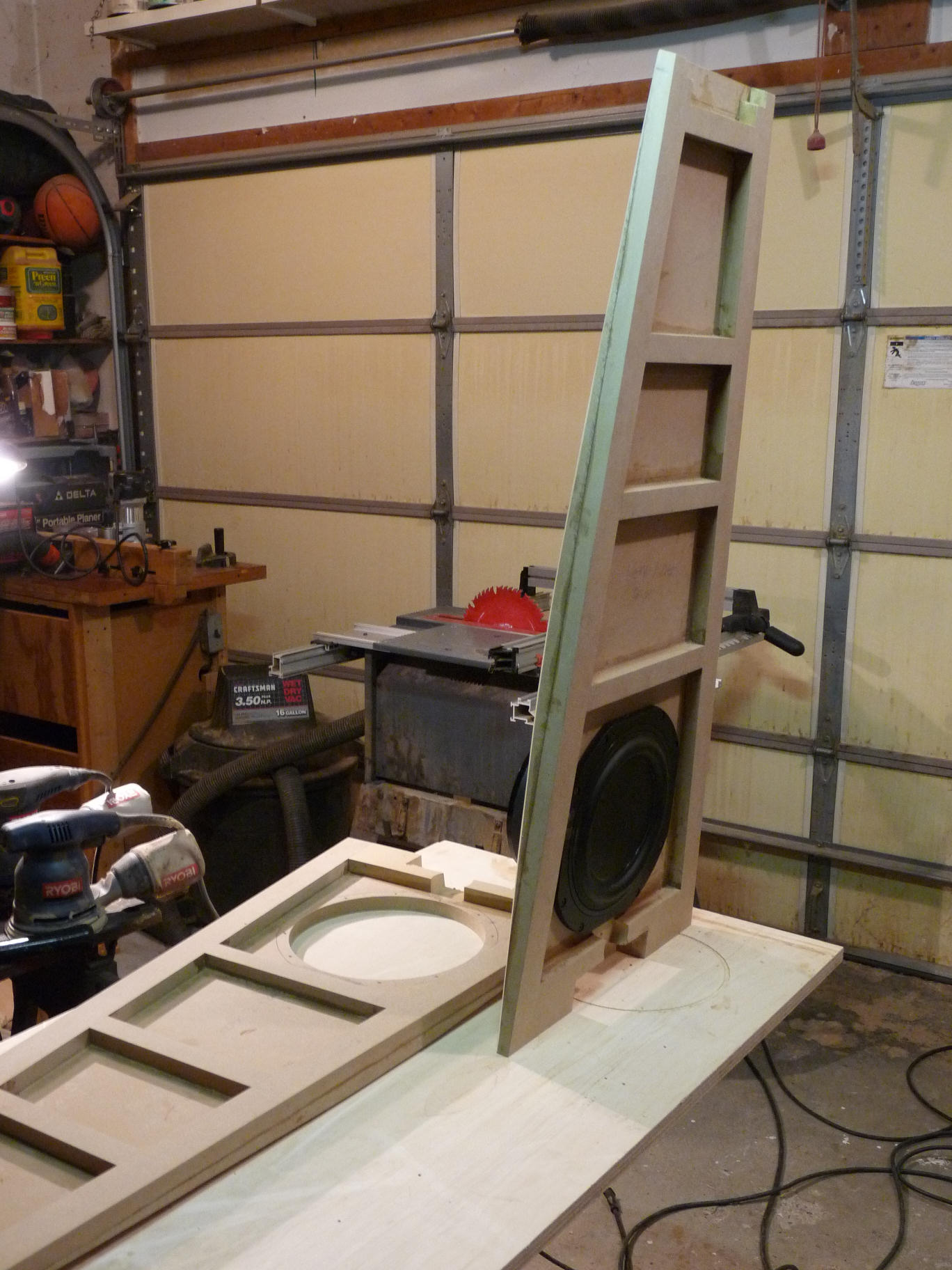
Enclosure Assembly:
This was a very complex enclosure to assemble and parts had to be cut and dry fit to ensure accuracy. Even though the 2d cad plans were as accurate and complete as I could make them, some reworking of parts were needed, either due to some unforeseen conflicts, or less than perfect angle cuts on the 4 outside tapered panels. Chamfers along the edges of the front and rear baffles were cut prior to assembly, using a table saw with a jog constructed to hold the panels at the proper angles. Rounding of the chamfers along the middle of the baffles were done by hand with a belt sander.
Construction adhesive was standard Titebond wood glue throughout. Body putty (bondo) was used in some places at panel interfaces, but later v-grooves were cut at these interfaces to seams from telegraphing through the painted finish and to compliment the overall aesthetic theme. The V-grooves at the panel interfaces and along the front center baffle were cut after enclosure assembly was complete.
Fiberglass resin was applied over the entire enclosure, both to make for a consistent surface upon which to apply paint, to treat raw mdf edges and inhibit seam telegraphing. This proved to be problematic in that the resin did not want to dry properly and some areas remained sticky to the touch, making it very difficult to sand, despite carefully following recommended hardener mix ratio and temperature recommendations. I’m not sure I can recommend that step unless you are already experienced and comfortable with this resin.
After sanding, several layers of primer, designed to cover fiberglass, were applied and sanded smooth. Once good, smooth coverage was reached, the preparation of each section departed. For the main box, I applied a couple layers of satin gray latex enamel paint with a super fine roller. The tweeter enclosure and the base of the speaker were done with black DuraTex, using a fine foam roller, followed by a chalkboard spray paint from Krylon to reduce sheen. The removable panel and slot port were also treated with black DuraTex, but then covered with a gloss claret red Rust-Oleum Painters Touch UltraCover 2X spray paint. Subtle hints of this claret red were also applied to the top of the main box, between it and the tweeter box, in the midrange box rear holes and also on secondary panels on the sides and front of the base.
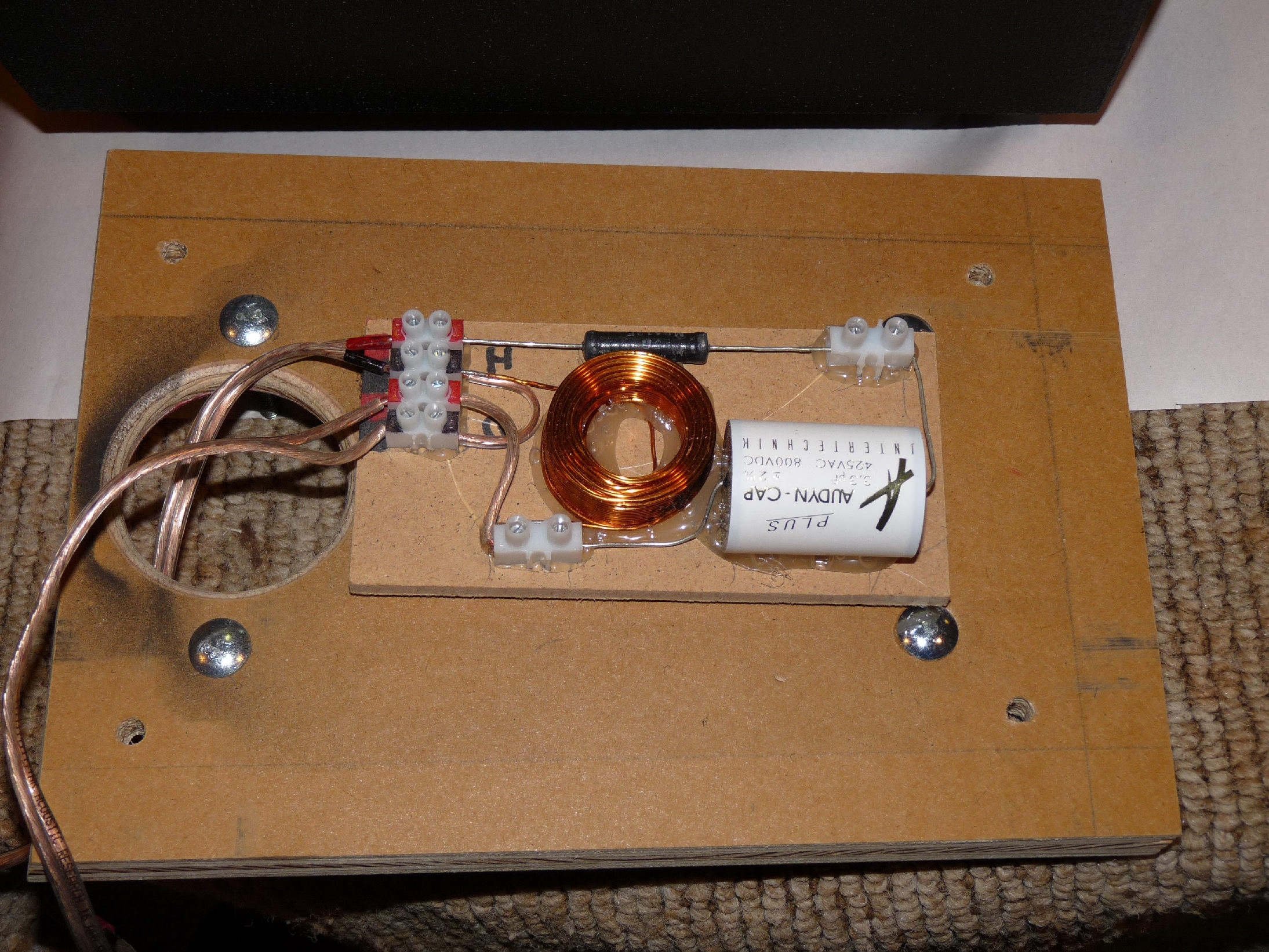
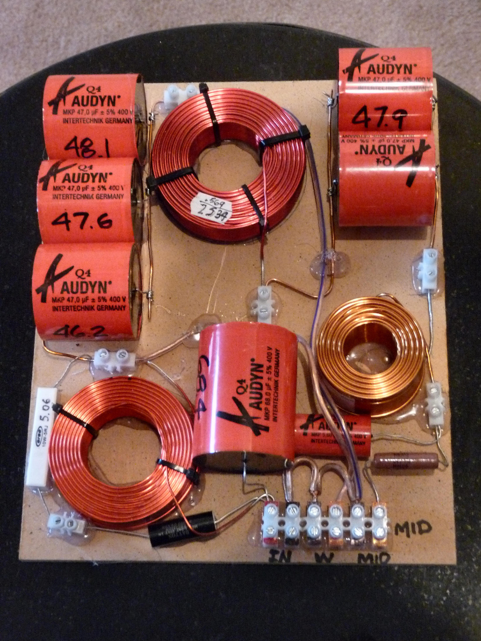
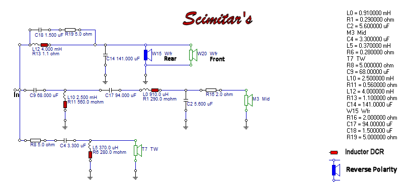
Crossover Design:
Crossover points are around 320hz and 2.4 khz. All drivers are wired with standard polarity, except the rear subwoofer, which is wired in reverse polarity. However, since the rear woofer is mounted inward, the reverse polarity keeps its output in phase with the front subwoofer. The 2.4khz point was felt to be ideal to match directivity between midrange and tweeter to retain as flat a power response as possible. Inductors are all air-core and caps are all polypropylene. The total parts used in the crossover design are 13, however the actual number of components are higher, as multiple 47 uF caps were paralleled to reach the cap values specified in both the woofer and midrange circuits. Power response is very flat, with a slight slope downward as frequency increases. This was predicted by digital MLS design measurements and confirmed by measured RTA in room results, which also indicate low end extension flat to 20Hz. Impedance and impeda nce phase are fairly flat, with impedance not extending below 4 ohms at any point.
Tips & Tricks:
It pays to create a jig to cut baffle chamfers with a table saw.
Chamfers around the midrange and tweeter, as well as tapered sides, can substantially reduce edge diffraction and increase aesthetic variety.
Use non-parallel sides to reduce standing waves and multi-layer/constrained layer construction, in addition to substantial bracing, to address panel resonances. Also, it is always best to make unsupported panel sizes differ so that any resonances are spread out and not concentrated at a specific frequency.
Different types of stuffing seem better at attenuating different frequency response ranges and sometimes the ideal results may come from use of multiple materials.
I would avoid the use of fiberglass resin if I were to do it again, though that might be due to my lack of experience in using it.
I used a combination of threaded inserts, cap head screws, carriage bolts, etc. to allow the both the top panel of the midrange box and bottom panel of the tweeter box to be removable, as well as the entire tweeter box. The use of a rubber spacer between the mid and tweeter enclosure provides vibration isolation and functions as a constrained layer damping system for both panels when bolted together.
Conclusion:
The results of this effort have been very rewarding. It was a very difficult speaker to both design and build, though the painted finish was quite easy, excepting the issues I ran into with the use of fiberglass resin. It is definitely a project only for advanced woodworkers. The Scimitar’s are full range speakers that are very effective as both Home Theater mains without separate subwoofers or as part of a 2 channel music system. These Tang Band drivers are some of the best I’ve used in each category, and sound great together. The RBM subwoofers could be effective as woofers in a 2-way as well.
About the Designer:
Dan is a member of the Parts Express Speaker Design Team. He has been designing and building speakers for over 10 years and has designed and built and/or developed crossover designs for more than a dozen award winning speakers during that time. He brings to the hobby a love for both audio and woodworking.
Project Parts List
these look amazing. they look like they sound amazing, too.
These look awesome. what would these compare to in sound?
Marvelous build! I dream of the day when I can fork the cash to build this for leisure. I am curious about the dual woofer design. Can someone explain the benefits of using this sort of dual woofer design, and also touch on the reasoning that one is reverse polarity? Thanks.
This is what is known as a “push-pull” woofer arrangement. You should be able to find lots of information if you google that phrase. Push-pull configurations reduce 2nd order distortion. Reverse polarity in the rear woofer is necessary due to its reversed mounting so that it’s output is in phase with the front woofer.
How can I contact you for any additional information on this build? I would like to chat more as I would like to possibly build these.. 30 years woodworking skills should help