KenA’s UBT’s
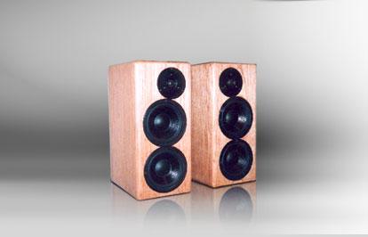

Designer: KenA
Project Time: 1-8 hours
Project Complexity: Hobbyist
Project Cost: $100-$500
Driver Selection
There are tradeoffs to consider when trying to cover the spectrum with only 2 speakers. If I was going to do a ported design I could have chosen a woofer that wasn’t as strong with bass. Though the Dayton woofers have good bass capabilities, they also have some weaknesses. Unlike the woofer response illustrated in the next section, the woofers I purchased, exhibit a dip or lull around 1.5 kHz., so they cannot be crossed high. Fortunately, the Dayton silk tweeter has a low Fs and can be crossed as low as 2 kHz. Since it is being padded down to reach the target system response of 82 dB, I was able to cross at 1.5 kHz and nullify the dip in the woofer’s response. Considering other possibilities, most of the woofers I looked at in the next price category up, can be crossed higher, but just don’t have the bass capability that this woofer has per the size box I wanted use. The Vifa P17J woofer could have been used without sacrificing any bass, but the box would have been nearly twice as large. One of my goals was to produce deep clean bass from a small box (under 1 cft.). The Dayton drivers are also inexpensive, which was enticing to a novice such as myself. In my opinion, they produce excellent sound for their price category and had some strengths to meet my requirements that more expensive drivers did not have.
Enclosure Design
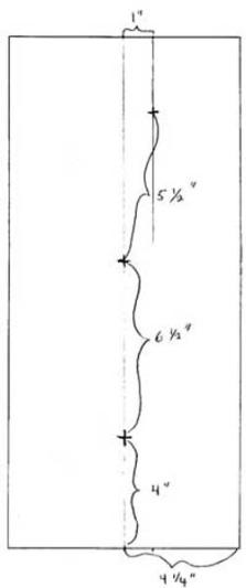
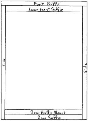
The suggested sealed box size for the Dayton 6.5″ woofer is .23 ft.^3 which yields a box Q of .71 and an F3 around 75 Hz. I chose to use a box nearly 50% larger (.335 ft.^3) which yields a box Q of .62 and an F3 of 76 Hz. with a single woofer. The shallower roll off helps accomplish the goal of extending the bass. With two woofers, the size is .67 ft.^3. I used a 3/4″ front baffle of 8 1/2″ x 19″ and 1/2 lb. of fill in each cabinet. A 3/4″ inner baffle is glued to the front baffle to yield a 1 1/2″ front baffle. The layout of the front baffle is presented below. The center for each of the drivers is shown. As you can see, the spacing is tight. A little extra space can be added between the woofers. There is already a little extra space between the main woofer and the tweeter. Of course, for the second baffle, the tweeter is offset to the other side. At the risk of overkill, I’ve included list of the pieces I used and illustrations of how the cabinets are assembled. The exterior dimensions are: 8 1/2″W x 12″ D x 19″ H. The pieces are 3/4″ thick. The are as follows: # 2 Front baffles 8 1/2″ x 19″ # 2 Inner front baffles 7″ x 17 1/2″ # 2 Rear baffle mounts 7″ x 17 1/2″ with a 5″ x 15 1/2″ square hole # 2 Rear baffles 7″ x 17 1/2″ with a 1/16″ shaved off top and one side # 4 Sides 11 1/4″ x 19″ # 2 Tops 7″ x 11 1/4″ # 2 Bottoms 7″ x 11 1/4″
Amplifier/Crossover Configuration
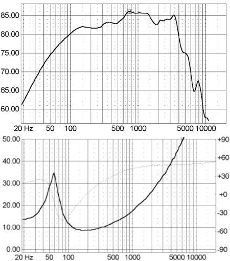
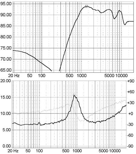
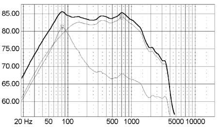
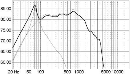
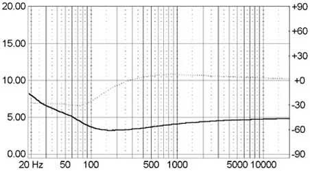
To fully understand the problem description, it is essential to be familiar with the drivers response and their impedance. Since I did not have a measurement capability when I began this project, I had to rely on others. PE Paul graciously gave me his measurements of the Dayton 6 1/2″ woofer. Paul measured the woofer in a box with the same baffle width, but larger volume. The SPL response in the bass region is not as critical to this design as the impedance for the size box used. Before I could finish this project, I had to measure the impedance in the actual box. I finished the project using a measurement taken by Dennis Murphy for me in my test box at DIY DC 2001. Paul’s SPL response and my impedance are shown below. Dennis Murphy also very kindly measured my tweeter at DIY DC 2001 in my test box. The project was difficult because of my dependence on others for measurements. Eventually, one of my silk tweeters went bad. Parts Express replaced it with a generation 3 tweeter. So I bought a second and switched to the project to the generation 3 tweeters. I got a measurement of that from PE Paul. The final outcome was close to what I modeled, but I had to interpret my model differently to get the desired results. I won’t elaborate, but will state that a mic preamp for SPL measurements is now at the top of my list. Rather than show every measurement I’ve looked at and used, I will use the ones above and will make a note of the final results where they are posted. My goal was to extend the bass by adding a second woofer to obtain a 6 dB gain and then throw away the extra SPL gained in the mid and high frequency range. There are two approaches I could have taken. First, I could have created a single crossover for both woofers that would have attenuated their mids and highs. This crossover would have been built around a large inductor with a resistor in parallel (something like 4 mH and 1.5 ohm). The second approach was to attenuate the lower woofer (the .5S woofer) and let the main woofer run full range to the crossover with the tweeter. This crossover would be built around an even larger inductor (8 mH). Both approaches had advantages and disadvantages. They also shared a significant challenge – the changing impedance close to the impedance peak at Fc. The first approach had a smaller inductor, but a larger cap and the mids would have gone through a resistor. It would have also required an MTM design to place the woofers equal distant CTC from the tweeter. The second approach has a larger inductor, but a smaller cap and no resistor for the mids. I chose the second approach. The problem with impedance arises from the need to begin attenuating response in the range where the impedance is changing rapidly. As can be seen in the woofer’s impedance graph, the impedance is changing rapidly below 100 Hz. The degree of significance of the changing impedance was not apparent to me when I first began. My initial thought was that I would use a large inductor and live with the “little” hump that would result from the impedance. The following graph illustrates the fallacy of this thought. I modeled a 24 mH inductor on the .5 woofer and a crossover on the main woofer. The target system response is around 82 dB. Ideally, the system response would follow the response of the main woofer down to 150 Hz. then continue at 82 dB down to 60 Hz. Two problems show up with this graph. First, the 6 dB rolloff doesn’t attenuate the .5 woofer enough and it contributes to the system response all the way up. (This problem is addressed in the Crossover section.) This could be improved a bit with an 8 ohm-47 uF cap zobel, but not enough. The second problem is the .5 woofer is not attenuated enough at the impedance peak and the inductor is already too big. It is starting to attenuate the response on the lower side of the impedance peak – attenuating the bass that I am trying to get. The next step is to use a 2nd order crossover on the .5 woofer instead of a 1st order, but this makes the problem worse. The graph below shows the effect on a L-R 2nd order crossover at 100 Hz. using an impedance of 8 ohm (25.4 mH and 99.5 uF). The 2nd order crossover does attenuate the response in the mid range, but it also changes the phase and begins to detract from the response of the main woofer. Also, for some strange reason, the peak is actually higher than it was before (87 dB instead of 85 dB). Alas, I had to admit to myself, there is no getting around the impedance peak – I had to do something about it. My first attempt to address this was to calculate an LCR circuit to flatten the impedance, but this would have been too expensive. I came up with a compromise that is a little less expensive – but still not as cheap as I would like. It required a large cap and resistor in a “zobel like” arrangement. By paralleling the .5 woofer with an 830 uF cap (yes, you read it correctly) and a 5 ohm resistor (two 10 ohm 20 watt in parallel), I was able to get the following impedance curve. There is still some change below 100 Hz., but it is much less significant. It is smooth enough to create a crossover for the .5S woofer. The impedance dips to 3.25 at 150 Hz., but this will change when the attenuation components are added.
Enclosure Assembly
The following is a pictorial with comments of the building process Christine and Michael followed. Anyone with minimal skills and tools can build these in one day. To construct the ubt they used a circular saw, router, $2 garage sale jigsaw, sander, and an old wooden bed frame and 4″ C clamps as a straight edge and saw guide. All construction was done on our 14′ x 12′ patio behind the garage. With instructions and classes, building the ubt was spread over a 2 1/2-day period instead of 4 to 5 hours. A scale drawing was done after converting the measurements from metric to inches. An order of construction steps was drawn up along with possible finishes for the ubt. The cuts were laid out allowing for the width of the blade cut and including an 1/8″ overhang on the front and back pieces to be flush trimmed with the sides. Front and back pieces were laid out using a centerline to retain an even angle to the top. Sides were laid out with a 90 degrees on the back of the pipe and the sloping angle to the front baffle. The distance from the edge of the saw base to the blade was measured and the blade width added. They measured this distance from the layout lines to clamp down the bed frame section as a saw guide. The last front/back piece was 1/2″ too narrow, so a piece of scrap was trimmed and butt-jointed a full 3/4 of the length by clamping both to a table over a strip of waxed paper. As the glue dried we found the oversize piece and trimmed it up while discussing the “measure 10 times, cut once” idea. After sizing up the cut pieces and doing a dry fit, front and back pieces were chosen and the ubt were glued and clamped. The pieces were glued flush at the pipe base allowing any excess in lengths from the odd angles to overhang the top of the pipe, which would be trimmed later. The sides were clamped to the fronts first allowing the 1/8″ overhang to be flush trimmed. Michael took over as Clamp master having helped on previous projects. It was 114 degrees and the glue was not waiting, so the ubt were glued up in record time. Screws and washers could be used in the absence of a large number of clamps. One construction note is the order we chose over Andy’s recommendations. He advises the woofer and tweeter recesses and cutouts be done to the front baffle and the fill installed before the last piece is glued. This allows the fill in the top half of the pipe to be easily installed and further tuning can be done through the woofer cutout. We elected to do the driver recesses and cutouts after the pipe was glued up and to install the fill from the open end and woofer cutout. I would recommend that the fill should be installed to at least the top 1/3 of the pipe before it’s buttoned up. Wadded up newspaper can be used to keep dust and chips out of the fill. But stuffing the pipe after it is together can be problematic because of the small dimensions at the top. A small end piece is installed before the back is glued and clamped. After it dried, a block and 60 grit sandpaper was used to sand it flush with the sides before gluing the backs on. After a quick safety lesson, the excess glue was sanded off the ubt and the baffle and backs were flush trimmed to the sides with the router. The excess at the tops of the ubt was trimmed using a square as a saw guide and the front baffle as the base. Here I allowed a break in the rules. After routing the driver recesses and cutting a through hole for the woofer with the jigsaw, they were down to their last blade and we needed that for the mouth openings. So out came the RotoZip to finish up. I was glared at for at least a half an hour when the last 2 holes were done in less than 30 seconds. The plans called for the baffle to be cut at the top of the mouth opening and 2 pieces glued to the side edges to finish the baffle. We elected to keep the baffle one piece. The mouth opening was roughed out with the jigsaw and finished with a flush trim router bit. A large piece of Plexiglas was attached to the base of the router to span the opening. A straight piece of scrap was clamped to the pipe forming a guide for the top of the mouth opening. Temporary bases were cut and attached to enable accurate measurements for the reflector piece. UPS arrived much like Christmas in the summer. Michael checked off the list and we were able to test fit the recesses and cutouts. I have to comment on the great service from Parts Express, but to deliver within 30 minutes of gluing the last piece is unheralded service. By the way, I haven’t seen that catalog since Michael got his hands on it. The last piece was the reflector. I had wanted to find the radius of the mouth cross section and install a curved reflector, but that was adding unnecessary complexity to the simple project idea. So we averaged the radius and came up with a reflector smaller than the plans. We decided to try it, and glued it at a 45-degree angle to the centerline of the pipe. With the cabs assembled a hole was cut for the terminal cup below the level of the reflector. Two sheets of felt were glued to the inside back of the cabs behind the woofer and tweeter. The top half of the ubt were stuffed with approximately 12 oz. of poly-fill down to the top of the woofer. A 3-wire harness was assembled and run from a hole through the reflector up a back corner to the speaker cutouts. The entire wire length was hot glued to the back corner to avoid wire rattle and vibrations. Michael and Christine each soldered up crossovers on a 5″ X 4″ piece of Masonite backer board. The crossovers were mounted to the bottom side of the reflector using 4 spots of hot melt glue on the backside of the crossover board and phillips head screws. The finish was left to Christine and Michael, and turned out to be the greatest amount of work. The ubt were sealed and sanded multiple times until a painted finish could be applied. Their original finish was to be a candy blue fading into a candy berrywine with a smoke black base. A trip to the local custom auto paints store left that plan by the wayside. Kustom Kolors candy lacquer was $50 a quart and that did not include the price of reducer or base coat. So on sale candy apple red and base were bought from the bargain bin. The ubt were first sprayed 2 coats of satin flat black lacquer for the smoke black. The tops were masked using low tack fine line tape and given 2 coats of silver base and 3 coats of candy apple. The stripe was again masked with fine line tape and airbrushed with 12-CT gold lacquer. 2 coats of cut high gloss clear were applied over the whole cabs. When the cabs are completely cured (in another 2 weeks) they will be polished out with 3M Perfect-it III finishing glaze and given 4 final coats of high gloss clear. Mouth opening and back are done in flat black industrial lacquer with light texture. The bases were cut from glued 1.5″ slabs and then a 1/2″ 45-degree edge break was cut. They are finished with Minwax colonial stain and 4 coats of Deft high gloss lacquer.
Conclusion
After the first stage of tweaking, Mike Keenan and I compared the UBTs to several speakers he has and they compared very well. The muddiness that was present in the midrange earlier was gone and they presented a very clear image. Now after the second, third, fourth, fifth …, rounds of tweaking, it is finished and I am very happy with the midrange. They have been improved significantly from my first crossover. I have finally padded down the highs enough and they are pleasantly sweet. The bass was good from the start. It can be felt in the floor – it is strong, clean and accurate. The sound of an acoustic standup bass is exciting. Getting an accurate measure of bass response is difficult because of room space and reflections. Using Paul’s measurement of the woofer, F3 is predicted around 45 Hz. Using the LspCAD box tool, F3 is predicted closer to 42 Hz. I created a CD with test tones (sine waves) spaced at 1/6th of an octave apart from 20 Hz. to 20 kHz. Based on subjective listening tests, I believe F3 is between 40 and 45 Hz (40 Hz. is where I could detect a difference first). Paul’s measurement was taken in a 4 pi setting. Since the UBTs are a sealed box design and are placed close to the wall (more like a 2 pi setting), there is more bass than what would be assumed or predicted from the measurement. When comparing the UBTs to the DIIIs, a speaker with a known F3 below 40 Hz., Mike and I found the UBTs to have bass nearly as deep, but not quite. This comparison was replicated later with Brent Langdon’s DIIIs. It is also possible that the shallow rolloff is creating an illusion that there is no loss in bass beyond the actual F3. Lest it be forgotten, though the UBTs are nearly as deep as the DIIIs, the cost to get that bass from a sealed design is 6 dB of efficiency. As stated above, this is a tradeoff I can live with easily. They are as sensitive as the Dayton IIs and the BR1s. Anyone considering this project would need to decide for themselves if the sealed bass sound is worth the extra cost. The .5 woofers account for about $76 of the project. If the boxes were made a little smaller (.6 cft.) and a 1.5″ D x 4″ L port were used, the f3 would be a little deeper. From my perspective, I like sealed bass. It sounds natural to me. I concluded that I couldn’t build a sealed sub that could blend in as well and do what the two .5 woofers do for anything close to $76, so it’s a good tradeoff to me. Needless to say, I’m very pleased with the outcome of this project.
About The Designer
This project was submitted by the venerable KenA, a frequenter of the Tech Talk board. Look for him there with questions.
Project Parts List
|
Part # |
Description |
Qty |
|
295-305 |
1 |
|
|
275-070 |
1 |
I’ve only built a couple projects and have the panels for this one all cut out. A little confused about baffles and tube details. Any sketches for these? How about the final crossover schematic? Thanks guys!