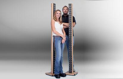
Kuze3201 Line Array


Designer: Darren Kuzma
Project Time: 20+ hours
Project Complexity: Professional
Project Cost: Over $1000
Driver Selection
A small 2″ drive unit useable as a mid-tweeter or extended-range midbass. Features include a black PPM cone, sturdy silver plastic basket, solid aluminum phase plug, shielded neodymium motor, s-shaped surround, and venting under the spider. Great for A/V, multimedia, and automotive use. Edit #1: Project edit: Due to current stock, the Tang Band W2-880S has been removed from the Parts List and is substituted with the Tang Band W2-803SM. The main difference between these two drivers is that the W2-803SM has a nominal 4-ohm impedance. The wiring diagram has been updated, and the final impedance is now a nominal 8-ohm load.
Enclosure Design
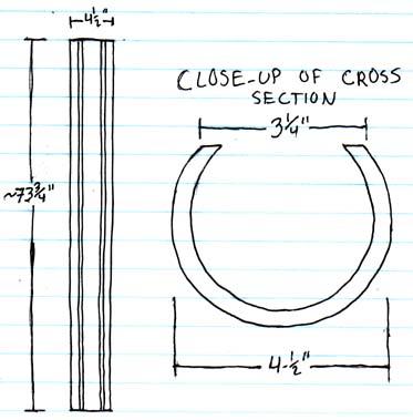
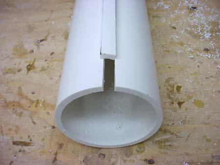
The enclosure was conceptualized using several key requirements: 1. A very small footprint to maximize the aesthetic effect of the line array, 2. Not wanting to build yet another square MDF box. The result of my searching for a new and interesting cabinet construction method was to use standard PVC schedule 40 pipe. Ideally the cabinet volume should be greater than that provided by a 4″ PVC pipe, but I decided to use it anyways. There were several reasons for this choice: 4″ PVC is less expensive, would be easier to cut, and would provide greater aesthetic effect. Plus my intent to use active equalization would mean I could adjust for any peaking that may occur due to an undersized box. To be able to mount the drivers to this PVC pipe, I decided that I needed a special mounting system. The drivers would be mounted onto their own faceplates, and then the whole faceplate could be attached to the PVC pipe. This required that a chord be sliced running the length of the pipe. From here, some endcaps would be placed on the ends, and a base would be attached.
Amplifier/Crossover Configuration
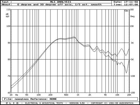
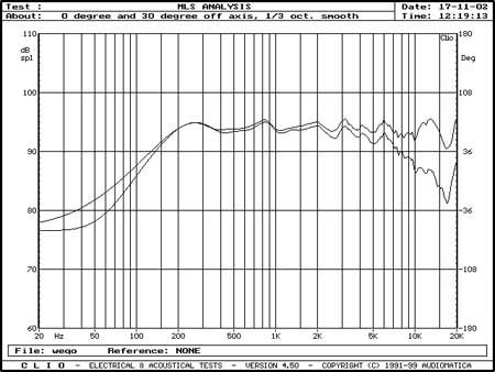
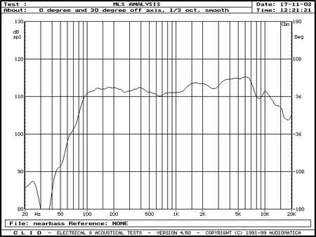
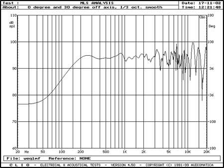
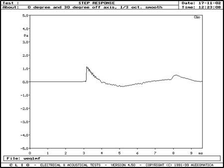
As this design was conceptualized to be used with an active equalizer, a standard passive crossover was not used. The equalizer that was used was a standard 15-band 12 dB graphic equalizer. The main corrections that needed to be handled by the EQ were boosting of the bass, and boosting of the top end. The midbass hump is a result of the small drivers with a high Fs and a correspondingly high box resonance frequency. Bass boost in the 50-120Hz region helped to fill-in the low end, and improve integration to the sub. While the drivers do have good extension up to 18K or so on their own, in a line array situation the high frequency boost helped to overcome comb filtering effects. Nominal Impedance is a healthy 4 ohms, and doesn’t dip below about 3.5 ohms anywhere. With all of the stuffing in the enclosure, the Q is not particularly high. Indeed, I believe it is actually less than .701. The frequency response is somewhat drooping without any EQ. This overall decreasing response must be an effect of the multi-driver integration, as a single driver does not show this drooping response at all. Because of the comb filtering effects at high frequencies, the F.R. graphs have been 1/3 octave smoothed. With the active equalizer in place, the top end is brought up back in line with the rest of the response. Notice that the off-axis performance at 30 degrees is not particularly poor. The nearfield measurement was used to show the effective bass output of the system. With the EQ in place, the F3 point can be manipulated to below 100 Hz. This works well for small rooms and low listening levels, but for high output situations, a slightly higher low-frequency cutoff is recommended. Just for informational purposes, the frequency response without smoothing. The jagged response that begins at 5K and worsens at higher frequencies is result of comb filtering, a very real measured problem. The step response of the system–note the single large step. This shows good phase coherency within the speaker. Unfortunately, the jagged nature of the step reflects the different arrival times of the impulse from varying driver distances.
Enclosure Assembly
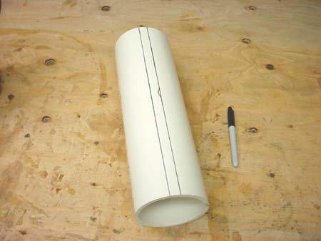
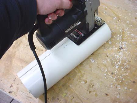
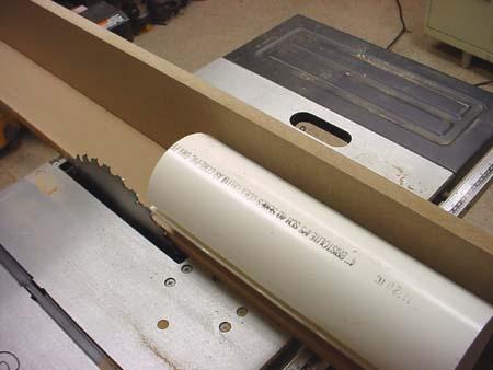
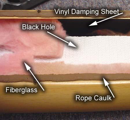
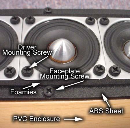
By far the most difficult part of the cabinet construction was cutting the PVC pipe lengthwise in a safe manner. I built an L-shaped jig using 3/4″ MDF, in which the PVC was secured with several drywall screws. This provided a stable and secure base that would allow the pipe to be slit without the possibility of rotating as the cut is performed. Because of my available setup, I chose to use my 12″ radial arm saw turned 90 degrees– a.k.a. ripping mode. This cut could also be performed using a table saw with a large blade on it. Even with the pipe secured, it was definitely still a dangerous prospect. I chose to use a fine-tooth steel blade, thinking that it would be a little safer than using big carbide-tipped blade. Also, I chose to make the two cuts running the length of the pipe in two different passes, rather than trying to do it in a single run. Indeed this turned out to be a good decision, as at the end of the lengthwise cut, the pressures within the pipe clamped up on the blade and had it deflecting a good 1/4″ from the outside edge to the arbor. Not very safe indeed! It turns out PVC pipe has a good amount of pre-tension in it, which makes it want to close up once it is cut. I have since devised a safer method for performing this dangerous cut. Begin by marking two straight lines perhaps 1/2 inch apart running the length of the pipe. Then cut along these two lines using a hand-held sabre saw. This will allow for a much more controlled cut without the use of large high-RPM blades. Once these cuts are made, this 1/2″ section can be removed and the tension can be released in a safe and somewhat predictable manner. After the pipe has been de-tensioned, it can be secured to the L-shaped jig and cut without and major problems. It will be the best bet to perform one cut, and then flip the pipe to perform a second cut. After the pipe was slit and cut to length, it is simply a matter of manufacturing some endcaps out of MDF and securing them to the pipe. To accomplish this, I simply placed the section of pipe onto a piece of 3/4″ MDF and traced the shape of the pipe. I then drilled several counter-sunk holes around the perimeter of the pipe and screwed into the end caps from the side. The screws and all holes used with the jig were filled with Bondo and sanded flush. A matching base was built out of a standard 12″ square of 3/4″ MDF. The edges were rounded over using a 1/2 inch radius router bit. Cosmetically, the pipe and base were finished by covering with Parts Express #260-016 beech vinyl wrap. Edit #2: Project edit: Due to current stock, the #260-016 may be replaced with #261-616. The following photos are a demonstration of the pipe slitting technique, but have been performed on a small section just for illustration. To attain some level of damping on the PVC pipe, I used multi-part system. Most importantly, a layer of the PE vinyl damping sheets was applied to all of the inner surfaces of the pipe. This does very well in terms of “deadening” the sound of the pipe. To further eliminate sound bleed-through, Black Hole was placed inside the pipe running the entire length. This combination effectively eliminated most noise coming through the pipe. Unfortunately, even with this treatment, there was still a “pipe” sound to the speakers. To further help absorb and eliminate these standing waves from the inside of the pipe, a relatively heavy stuffing of pink fiberglass was used. Together, this combination of damping and absorption is very effective at making this speaker sound as if it is not in a piece of PVC From the beginning of this project, I knew that I was not going to be cutting 64 little 2″ holes. So, I devised a method of mounting that uses a series of jagged pieces of plastic as a sort of mounting plate to simplify the process. First, I made a 1/4″ MDF template based on what I wanted. I then ripped 16 strips of 1/8″ ABS plastic sheets, roughly 2″ wide by 24″ wide. I taped these together into stacks of 5, then traced my design and cut the notches using a band saw. These pieces then became my mounting flange. See below for a picture. Once the mounting pieces were cut to size and cleaned up, I affixed a thin layer of self-adhesive foam sheeting to each piece. This would allow for a somewhat air-tight seal to help prevent chuffing and spurious noise from escaping the enclosure. Each section of ABS is notched for and is long enough for 8 drivers. It works out well that this is also the number of drivers that are wired together in parallel. This allowed me to essentially make totally separate segments consisting of 8 drivers a piece. The individual drivers were secured using some 3/8″ black self-tapping screws that are normally used in metal-stud construction. This allowed me to simply screw each driver into the faceplate, without any pre-drilling. Once each section was complete, I filled the crack between the drivers with a squirt of hot glue. The drivers are connected in a standard sereis/parallel configuration, with 8 drivers in parallel, and 4 of these sections in series, resulting in a nominal impedance of 4 ohms. The wiring was done with standard 16 gauge hook-up wire. Rather than cut and strip 128 little pieces of wire, I found that I was able to use one long piece of wire that was stripped periodically and soldered. I used a pair of side-strippers, like PE #360-640 to do the stripping. These strippers are great, and without them I wouldn’t even want to attempt the wiring. Edit #3: Project edit: Due to the driver change, wiring the drivers is slightly different. Eight groups of four speakers are used. Each group of four is individually wired in parallel, each group is then wired in series. Please refer to the included schematic.
Conclusion
Overall, the speakers are very good sounding, though it definitely sounds different than your standard 2-way bookshelf speaker. The sound is very large, with a good sense of soundstage width and height. I would say that they have a “live” sound, which is great for rock and similar music. They definitely can play loud and clean when mated with the appropriate subwoofer. Because of the non-tapered line, they great in situations where listening is not occuring precisely in one location, particularly in the vertical plane. This makes them perfect “party speakers” or speakers for the person who listens to music while they do other things. For an audiophile-sort who likes to sit in his sweet spot and sip brandy, these probably aren’t the best choice. It was described at DIY2002 Dayton that the imaging was a little loosey-goosey. However, I found from my experimentations that there was a solid image when seated precisely between the speakers, but the sweet spot is rather small. Several people noted that the high-frequency reproduction lacked some “life” and “air”. This could be attributed to the comb filtering problems that definitely were occuring. However, this also could be a result of the high-frequency capabilities of this particular driver, it is hard to say for sure. Whatever the reason, for pure audiophile use I would consider these lines to be slightly less “refined” and “articulate” than many standard speakers. One of the other key aspects of this setup is the proper subwoofer integration. Because of the fairly high crossover point the proper crossover frequency on the sub and the relative level can make or break the sound. When everything is dialed-in correctly, the transition from sub to satellite can be quite good, however it does take some tweaking to achieve a good integration. The results of this experiment definitely show the capability of using small and/or low excursion drivers successfully in a line array situation. However, it does illustrate the potential problems of center-to-center spacing in high-frequency performance. Comb filtering is a definitely a legitimate issue. With regards to power-tapering vs. not power-tapering, I am still somewhat up in the air. While tapering may help to solidify the image, it does take away from the “sound is coming from directly in front of you” effect.
About The Designer
This project was submitted by Darren Kuzma. He frequents the Tech Talk board, so feel free to post there with any questions about this design.
Project Parts List
|
Part # |
Description |
Qty |
|
264-805 |
1 |
|
|
265-948 |
1 |
|
|
091-1245 |
1 |
|
|
261-616 |
1 |
looks amazing!
The wiring diagram shows groups of 4 speakers where they are wired in parallel so the impedance is 1/4 of the 4 ohm individual speaker impedance. Then there are 8 sets of the 4 speaker groups wired in series. That should give 8 ohms total impedance for the array? Is that correct?