
Act 2

Designer:
Neil Davis
Project Category:
Home Electronics
Project Level:
Advanced
Project Time:
8-20 Hours
Project Cost:
$100 – $500
Project Description:
Act 2 is the second in a series of designs that will result in a compact yet potent wireless 2.1 active system that can be used for computers, TV’s and other entertainment equipment. Act 1 was a subwoofer using a Dayton Audio B-REX cabinet with two Tang Bang W5-1138SMF subwoofers and a Yung SD-100 plate amp. For Act 2, we will remove the B-REX back panel and Yung amp and replace it with a 6-channel amp and a DSP board on an aluminum plate—it will be our own plate amp. This project focuses on that new plate amp design and how the power supply, DSP, amps and WiFi board get mounted and connected. The satellite speakers are described in the write-up for Act 3, and the software and how it gets loaded will get addressed in Act 4.
This project also describes a smaller version of the plate amp that can replace a Yung SD-100 amp. This second plate amp uses an external power supply and a “double-decker” construction to accommodate all the electronics.
Design Goals:
The overall design goal for the Act series is to create a DIY version of the Sonos, Heos or Bose active WiFi speakers, but with better audio quality. It’s hard to compete with these commercial products on size, as some of them are surprising good given how small they are. But by using larger cabinets we can improve on the sound quality and still have the convenience and flexibility of a modern multi-room high resolution WiFi system, at a good price point. And with some attention to materials and detail, we can also make nicer looking cabinets (see Act 3 for some interesting cabinets).
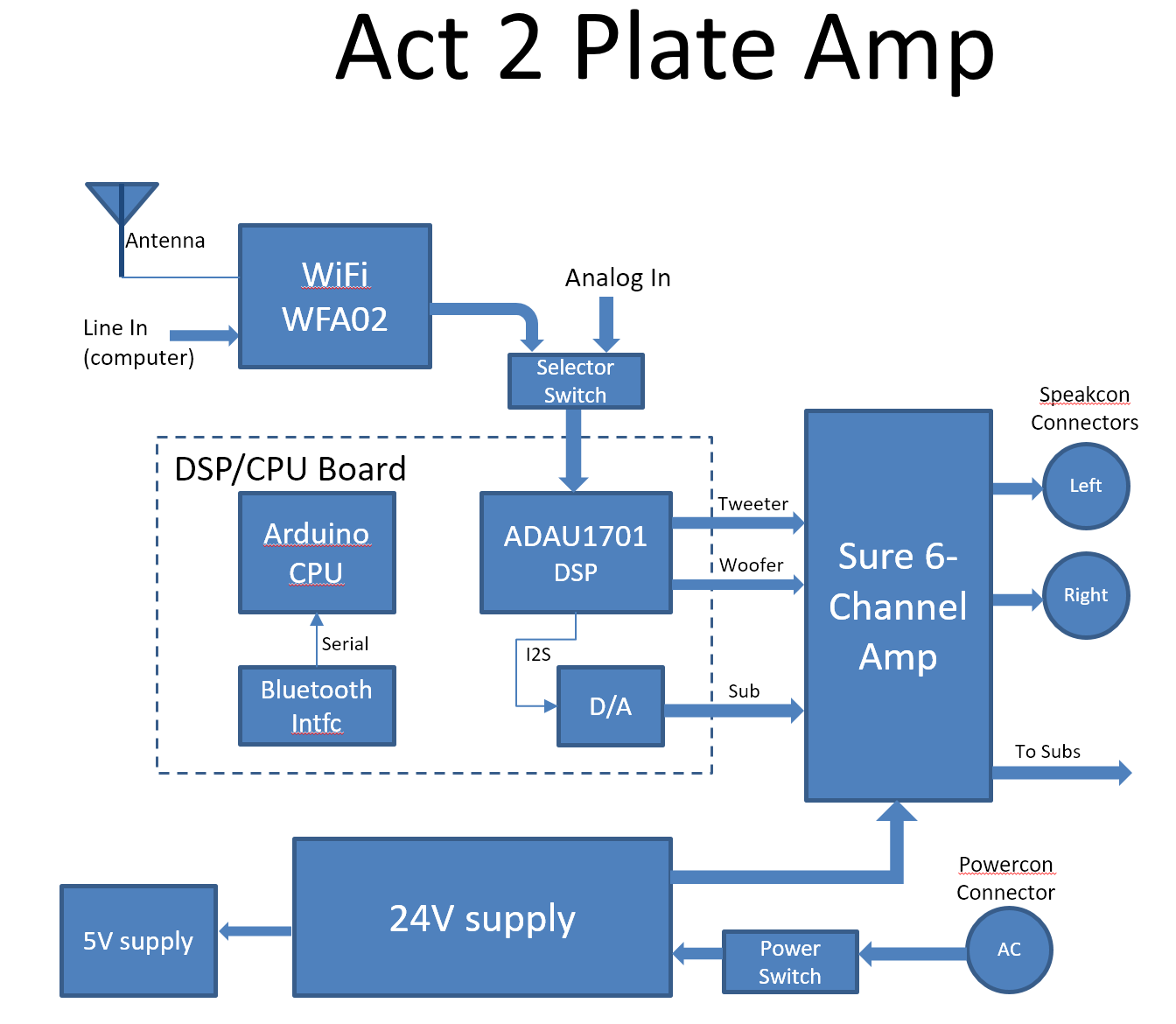
The key to this high audio quality WiFi capability is the electronics on the plate amp. The block diagram shows the components that were used for the plate, and the next sections describe the various components and why they were chosen.
Driver Selection:
The drivers are described in the next project: Act 3. For this project, we needed to select the amplifiers, the power supply, the DSP board and the WiFi module. Each of these components are described in the following sections.
Amplifier: The design goals include a subwoofer with 2-way left and right active 2-way speakers, so I needed an amplifier with a minimum of 5 channels (subwoofer, left woofer, left tweeter, right woofer and right tweeter). Since the Act 1 subwoofer uses 2 drivers, a 6-channel amp was preferred. I didn’t want to deal with heat build-up so I only looked at class D amplifiers. Class D amplifiers switch at high rates and the switching currents and magnetic fields in the output inductors can cause problems when trying to use multiple two-amplifiers near each other. So, the logical selection was the 6-channel Sure amplifier, PE part number 320-307. This amp uses three of the TDA7498 chips synchronized to the same clock, so the amps will not interfere with each other.
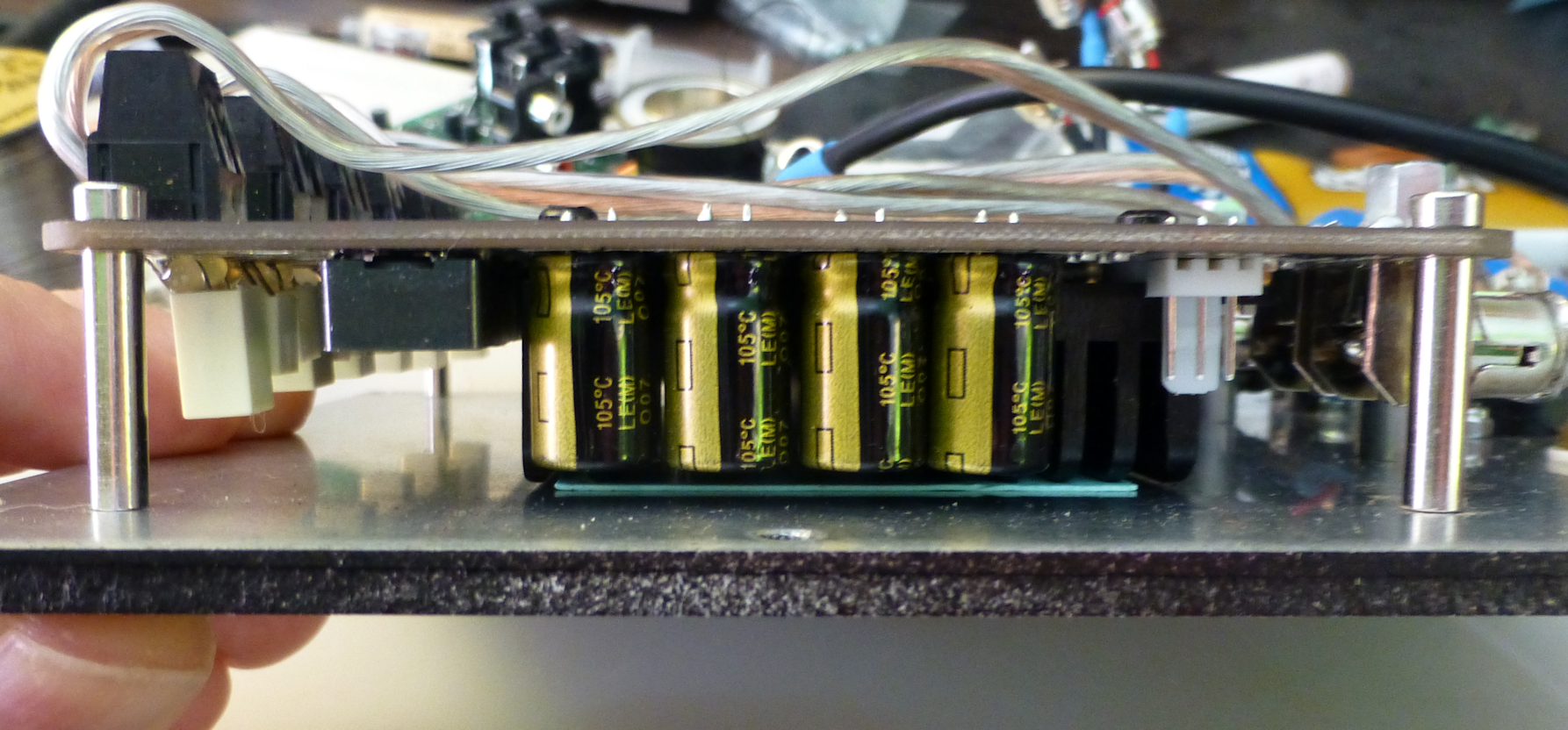
The TDA7498 is a well-designed class-D amplifier IC, and we can count on reasonably good audio quality from this amp. The amplifier comes with a small fan to blow air across the heatsink. You will need to remove the fan, as we are going to mount the amplifier “upside-down” and thermally connect the heatsink to the mounting plate. To ensure a good thermal connection, use a .5mm thermal pad between the mounting plate and the heatsink. When you use the 20mm standoffs in the kit mentioned below, there will be enough pressure from the mounting screws to provide a good thermal connection. There is a picture that shows the blue-green thermal pad between the mounting plate and the heatsink.
Power Supply: The power supply is the Meanwell 150W 24V switcher for the larger plate amp, and for the smaller plate you will need just about any competent 100W-150W external “brick” type power supply. A larger power supply could be used, but a nice feature of active 3-way systems is that you can typically get by with smaller amplifiers and power supplies than for similar passive systems. The 100W to 160W power supplies work very well for this application.
DSP/CPU Board: As you can see from the block diagram, there is a lot happening on the DSP/CPU board. I used a custom design for this board to keep the circuitry compact and avoid wiring between submodules. The CPU, DSP, DAC, local power supplies, and Bluetooth/USB are connected by traces on the board, and the only external connections are the audio lines (which use RCA phone jacks), power and some serial connections.
Because this is a custom DIY board, you will have to build this board yourself or find someone who is making them. Design files for the PCB and some construction details are available on the Audiodevelopers web site. It is not an easy board to assemble because of the large number of SMD devices. However, there will be an updated version of this board that will be much easier to assemble. The new design will use a greater number of pre-assembled modules to reduce the parts count and make assembly much easier. That design will be posted on the Audiodevelopers web site and be available for free once it is finished and debugged.
Although this plate amp design uses the custom DSP board, it is possible to use separate modules. For example, you could use a miniDSP board or FreeDSP board, but would need to add an Arduino CPU, a Bluetooth board, and an extra digital-to-analog converter board. That’s not too hard to do, but the size and cost and wiring complexity make that approach cumbersome. There is a place reserved for an article that shows how to use these other modules on the Audiodevelopers web site (see the Article on Case Study #2).
WiFi Module: WiFi based wireless speakers are the rage and no doubt the future of home stereo. According to a report from Strategic Analytics, this market grew by 62% in 2016 to 14 million units. Sonos was one of the early market leaders, but Bose, Denon, Amazon and others have jumped in with products that range from background music devices to replacements for the home stereo. These WiFi speakers allow you to set up a home network of devices with routing of various sources to any room in the house. The WiFi speakers have built-in Internet radio (XM, Pandora, Spotify, Amazon, Google, etc.) and allow music library playback with smart phone control.
Parts Express carries two different WiFi modules—the WFA02 (#300-576) and the WFA28 (#300-577). I used the smaller (and cheaper) WFA02 module. Both are controllable with the same smart phone app, and both offer the features we need for this project.
Enclosure Design:
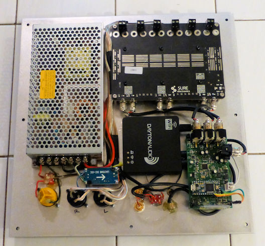
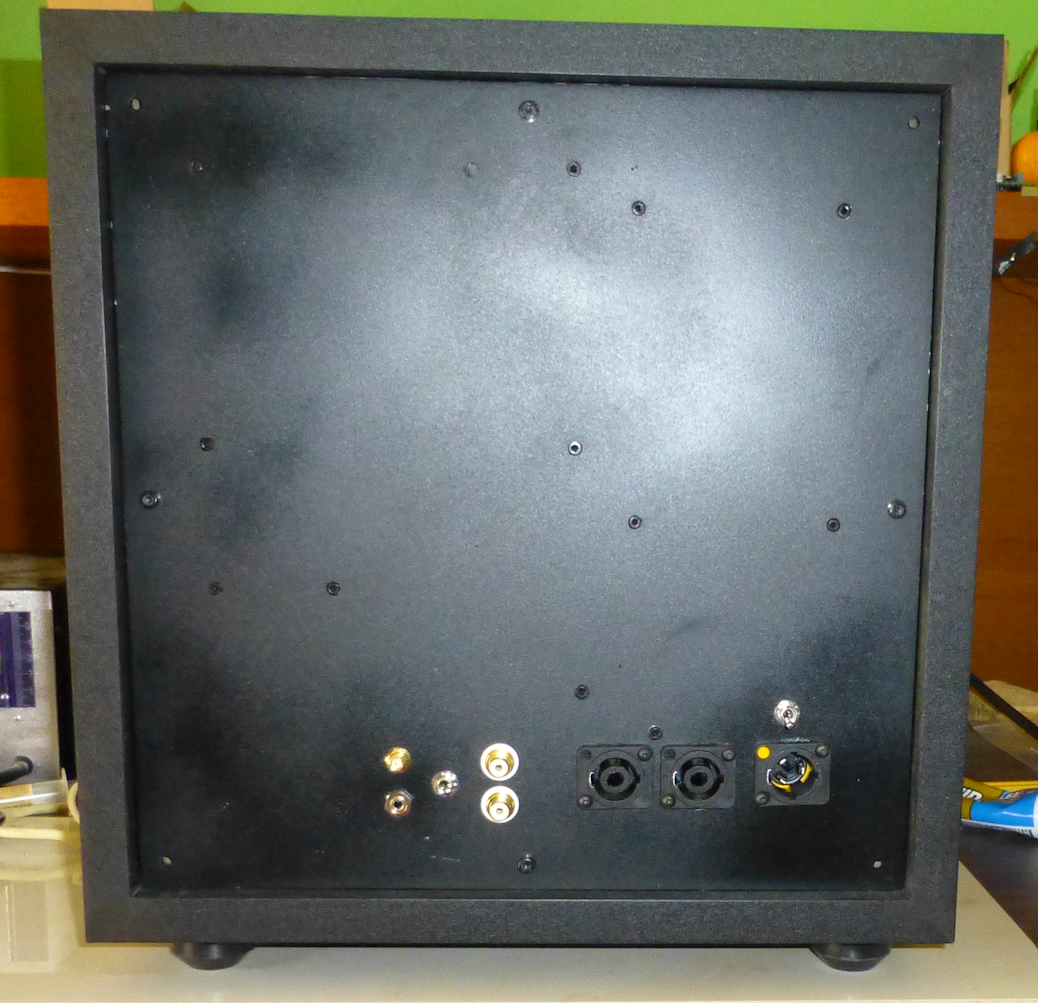
The electronics are mounted on a plate that fits in the back of the Dayton Audio SWC1-BK 1.0 cu. ft. cabinet (PE #302-836). This cabinet is well built and it provides plenty of space for the Act 2 electronics.
The first step in building any plate amp is to lay out the parts so they fit on the plate. This can be done by using “paper dolls” of each component or using a computer drawing program. I used Powerpoint to create the components using a 2:1 scale, and move them around on the plate to make sure everything would fit. The Act 2 plate layout graphic shows that the parts fit with little room to spare. There is also a layout for a comparable plate amp using the Sure DSP boards. Even with the extra modules, there is enough room on the plate for everything. But with the Sure modules, there isn’t enough room to use the bulky RCA connectors as interconnects, so the cabling will be more involved.
The SD100 replacement amp is much smaller than the 12.5” square plate amp, and it is clear from the layout that the power supply will need to be external. And even without the power supply, the 7” by 8” plate needs a second layer to make sure the components fit. I used a 1/8” thick plate of aluminum that I had left over from my wife’s business. The guys in the machine shop where I worked had made her some nice aluminum cookie sheets in exchange for some cookies, and I was able to cut the cookie sheets down to the right size on a bandsaw. So, if you don’t have extra aluminum plates laying around, you will need 2 pieces of 6” by 6” 1/8” material. One of the pictures shows the double-decker construction for the SD100-sized amp.
Enclosure Assembly:
The assembly phase involved a lot of drilling, component mounting and wiring.
Drilling: It’s important to drill all the holes you need to mount components before painting and assembling the parts. Drilling is messy, and you don’t want metal flakes shorting out circuitry that is already mounted. The hole locations and drill bit sizes and countersinking will vary depending on the selected connector hardware and the modules you use. Take your time on this important step, and keep double-checking for the right fit for each item. Once the holes are drilled, you can sand the plate with increasing fine paper until you get the “texture” you desire. You don’t need to paint the aluminum plate, but a coat or two of flat black will be less conspicuous and easier to get past your wife.
The power supply has pressed-in threaded inserts for mounting that are difficult to accurately locate. Fortunately, the power supply has a plastic insulator that easily slides out after removing one screw located near the power input connector. Just mark the insulator with a pencil through the mounting holes and then slide out the insulator sheet to use as a template. For the DSP board, just make a printout or the PCB or one of the Gerber files to locate the mounting holes. Once you drill these holes for the M3 screws (1/8” will give a tight fit), countersink the cap screws with a 5/32” drill to a depth of 1/8” from the front side of the plate.
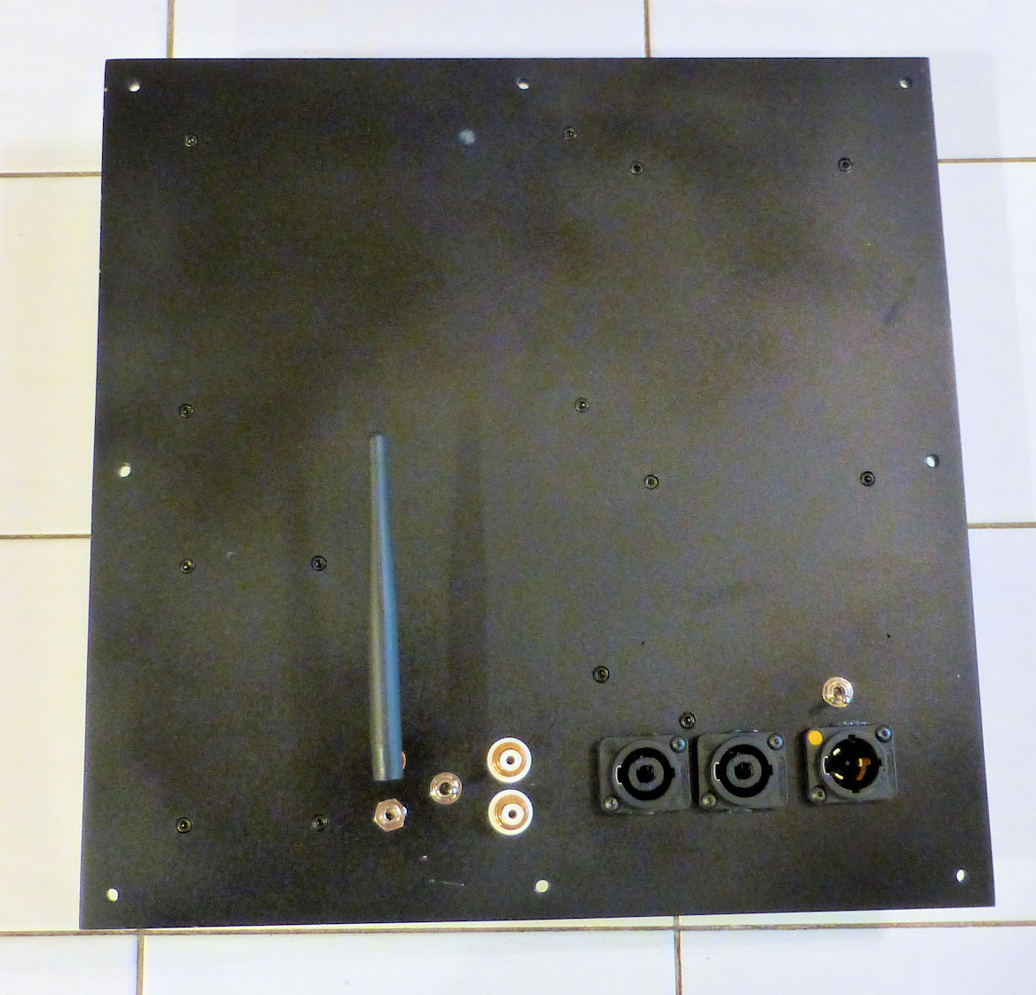
The Speakon and Powercon connectors require an “oddball” 24mm drill size. Since this is not a common size for most drill bit kits, you may have to order one online. I bought a 24mm “Roman Carbide” Forstner bit from Amazon for $13. However, after drilling just 2 holes in the aluminum plate, one of the carbide blades broke off. By the time I was done with all the holes, both carbide blades had separated from the body. You might want to either buy a better drill bit or else be very careful to not press too hard with the budget drill bit.
Notice that many of the components on the plate require countersinking from the back due to the thickness of the plate. You might be able to find some panel-mounted switches and connectors suitable for ¼” panels, but you will probably have a better selection of components if you just countersink everything with a large bit. If you are building the SD100 version, you might need to shop around for a heavy-duty power connector. There are 5.5mm/2.5mm barrel connectors that can handle 5A, but the ones PE carries are only rated for 3A.
You don’t need mounting holes for the WiFi module, as that plastic box can be affixed with Velcro or the 3M mounting strips used for toll road transponders.
Assembly and Wiring: Assembling the components to the plate is fun, as you get to see the amp take shape. But wiring seemingly takes forever, and there is little joy in crimping pins on small ribbon cables or soldering RCA connectors to shielded cables. Plan to fight the tedium by having good beer or stronger spirits to keep you amused, and don’t get frustrated at the amount of time it takes—that’s just the nature of this task.
A step that requires some extra care is wiring up the external antenna to the WiFi module. You only need to do this if you can’t get a good WiFi signal with the module hidden behind that mounting plate. If you are close to your WiFi router you will probably get an adequate signal. But our router is in the basement, so I wanted an external antenna, even though I knew this would void the warranty. Carefully open the WiFi module using a knife blade to pry off the cover. Then remove the 4 mounting screws holding the board to the plastic housing. The button for the WPS switch is probably going to fall out, so make sure you don’t lose it on the floor. Then remove the antenna connector—it is one of those tiny U.FL connectors that you see in laptops, and it’s got hot melt glue that you need to pull off. I used a U.FL to RP-SMA cable assembly (Mouser part #741-080-0001) to allow using a nice external antenna. With the external antenna, the signal strength was about 98%, even though I was two floors up from the router. If you have a hot melt glue gun available, put a small blob of glue on that UFL connector to make sure it doesn’t fall off the board (that happened to me!). When you put the board back in the case, make sure you remember the WPS button, because you will need it to get the WiFi module to join your network.
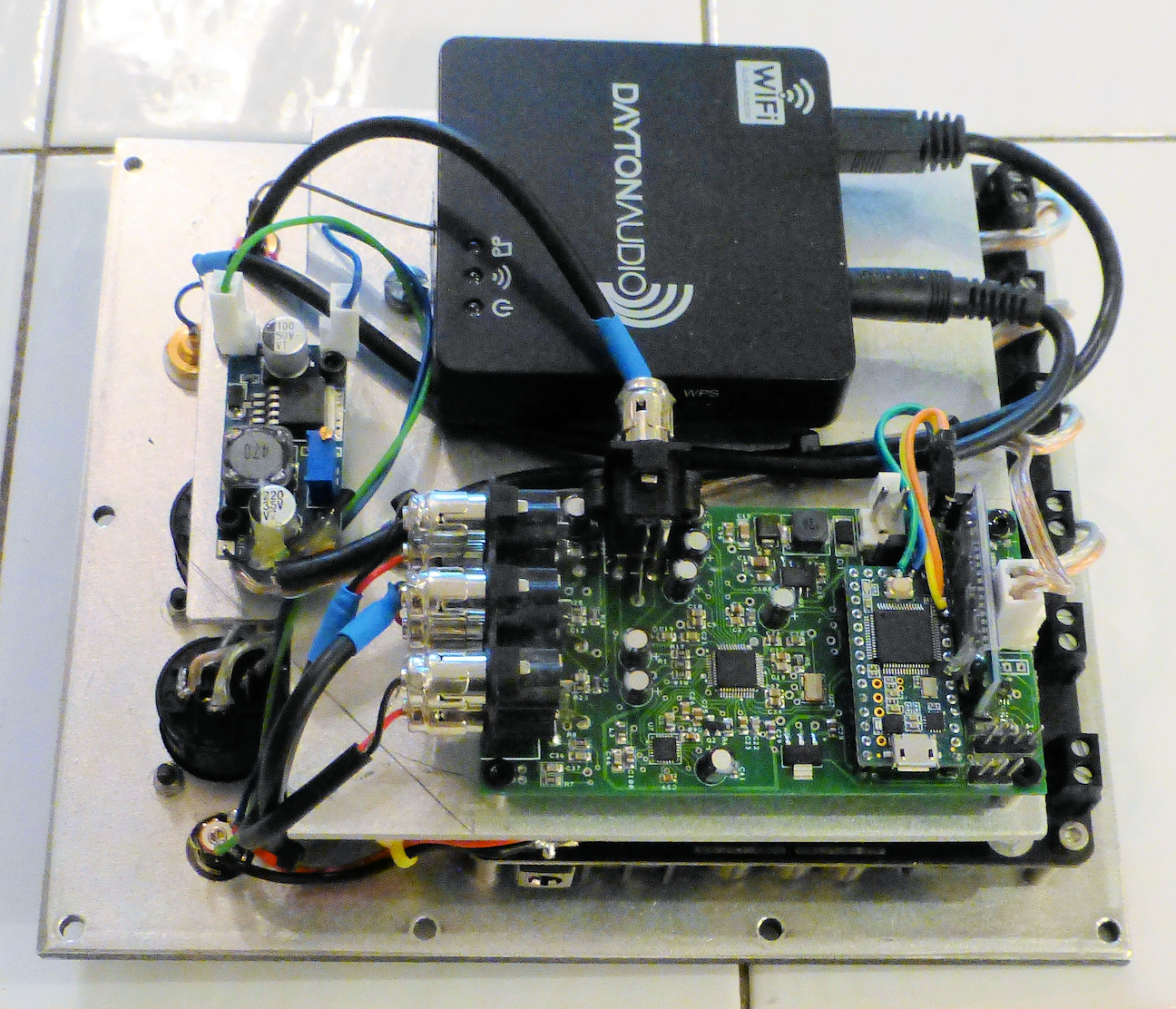
Unfortunately, the original wiring approach had issues with grounding. The WiFi module requires +5V at around 300ma, and most of that current is for the WiFi signal, which in effect is a small radio station. When you try to connect the audio to the amplifier or DSP, all that return current is flowing through the ground, and it creates an audible noise like digital chatter that is annoying. It would be nice if the WiFi module had separate analog and digital grounds that could be connected independently, but that’s not the case. There may be other ways to fix this grounding issue, but the easiest approach I found was to either use a DC to DC isolating convertor for the WiFi 5V, or else run the WiFi from a USB charging module. The noise goes away once the power is isolated. The new version of the DSP board will include the DC-DC isolation module, but for this prototype I used the USB charger.
Crossover Design:
The crossover is active, using an ADAU1701 DSP chip that is controlled by an Arduino CPU. Act 3 describes the active crossover design, and Act 4 describes the software that is used to control the DSP. Act 4 also describes the cell phone application that is used to select the crossover and EQ.
Tips & Tricks:
This project requires loading software into the CPU. Unfortunately, software is never done, so it is helpful to extend the USB connection to the CPU by adding a connector to the outside of the box. The Neutrik NAUSB-W-B (PE part #092-279) and a short micro USB to USB cable (PE #130-572) let you easily provide an airtight USB connector on the subwoofer front baffle. There’s not enough space on the back panel using the layout shown here, but having the connector on the front is a convenience.
Another important tip is to make sure you set the switches on amplifier that adjust the gain before you mount it to the plate. Since the amplifier board gets mounted “up-side-down”, these switches will not be accessible once the amp is installed. There are some calculations that you can do to determine the best gain value for each channel, based on the power supply voltage and the sensitivity of each driver. For many designs, the best switch settings will be “weak” (25.6dB) for the tweeter and subwoofer and “low” (31.6dB) for the woofer or midrange.
Conclusion:
This is a complicated project, and it is only part 2 of a 4-part series. Most of the real complexity is hidden inside those powerful modules: the WiFi adapter, the DSP, the CPU, or the Bluetooth adapter, the 6-channel amplifier and the power supply. But there is still a lot of cutting, drilling, wiring, assembly and finishing to complete this phase, and then there’s that big step of loading software in part 4 that still awaits us.
This is still more of a prototype than a finished solution, but it helped identify what is needed for DIY’ers to make a high-end DIY Sonos/HEOS/Bose clone that they can customize and use drivers of their choice. This project made it clear that the DSP board is a good step forward, but that a next-generation version will make this project easier to build and simpler overall. And there might be a kit down the road to make that DSP board easier to build or there might be something fully assembled that you could purchase.
But even as a prototype, this project is fun to use and extremely satisfying. The Dayton WiFi software is not as “professional” as the Sonos or HEOS equivalent, in that there are fewer “stations” (for example, Sirius and Pandora are not natively supported) and less integration for some of the existing stations such as Spotify. But there is still a good variety of Internet streaming sources, and the multi-room routing and lossless audio is great. The WiFi module can keep music libraries on a memory stick, or it can play from music libraries located on your phone and other computers. That’s a lot of flexibility and fun, combined with high quality audio.
The DSP board adds even more fun and excitement. There is an Android app that will run on a cell phone to select crossover slopes and frequencies or specify EQ, baffle step compensation and bass boost. Those features will be described in the next project (Act 3).
About the Designer:
Neil is a member of the PE speaker builder design team (SBDT). He is a retired engineer who has enjoyed watching the speaker building technology evolve and he wants to help bring those technologies to the DIY community.
Project Parts List:
Looks like you’re the technologically advanced builder here in the community that could possibly answer my question. I recently acquired a wireless sub at a thrift store and would really like to turn it into good ol’ wired sub for my bedroom theater. Is there any way to do it? It’s klipsch r-10b and I really like the looks of it and how it’ll fit in the bedroom scenario. Many thanks in advance!