The Mavericks


Designer:
Mike P
Project Category:
Tower Speakers
Project Level:
Intermediate
Project Time:
20+ Hours
Project Cost:
$500 – $1,000
Project Description:
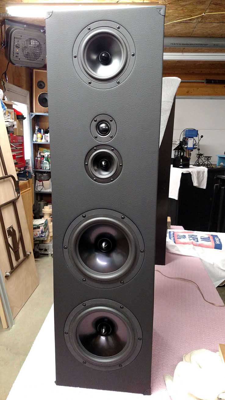
The Mavericks – 5 driver, 4-way floor standing tower speakers
Design Goals:
There were two things I hoped to accomplish with this build. First, I wanted to build a pair of floor standing tower speakers utilizing all of the Dayton Audio drivers I purchased at the 2015 PE Midwest Audiofest. Second, I wanted to incorporate the suggestion that I received from the speaker competition judges on my first tower build which was to improve the cabinet astetics.
Driver Selection:
RS100-4 mid-range 295-378
RS150-4 mid-woofer 295-372
RS225-8 woofers 295-356
ND25FA-4 soft dome tweeter 275-059
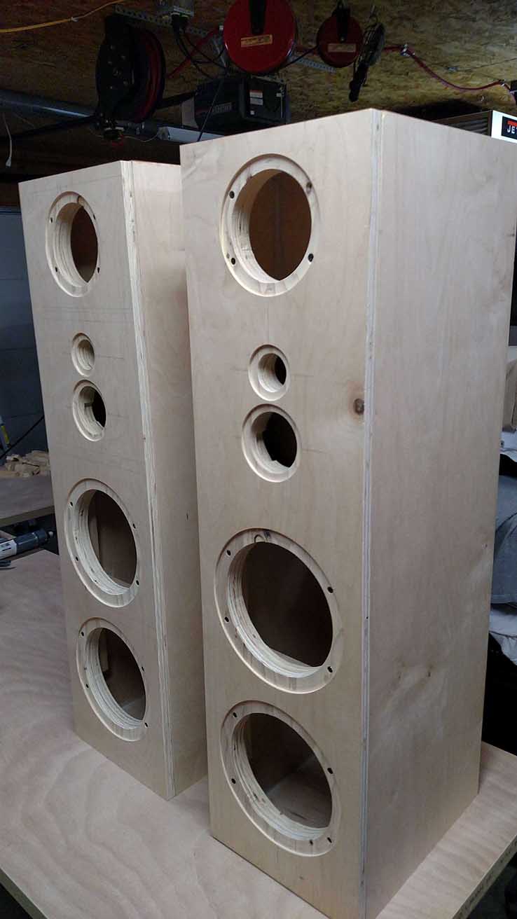
Enclosure Design:
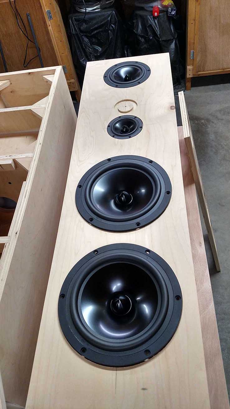
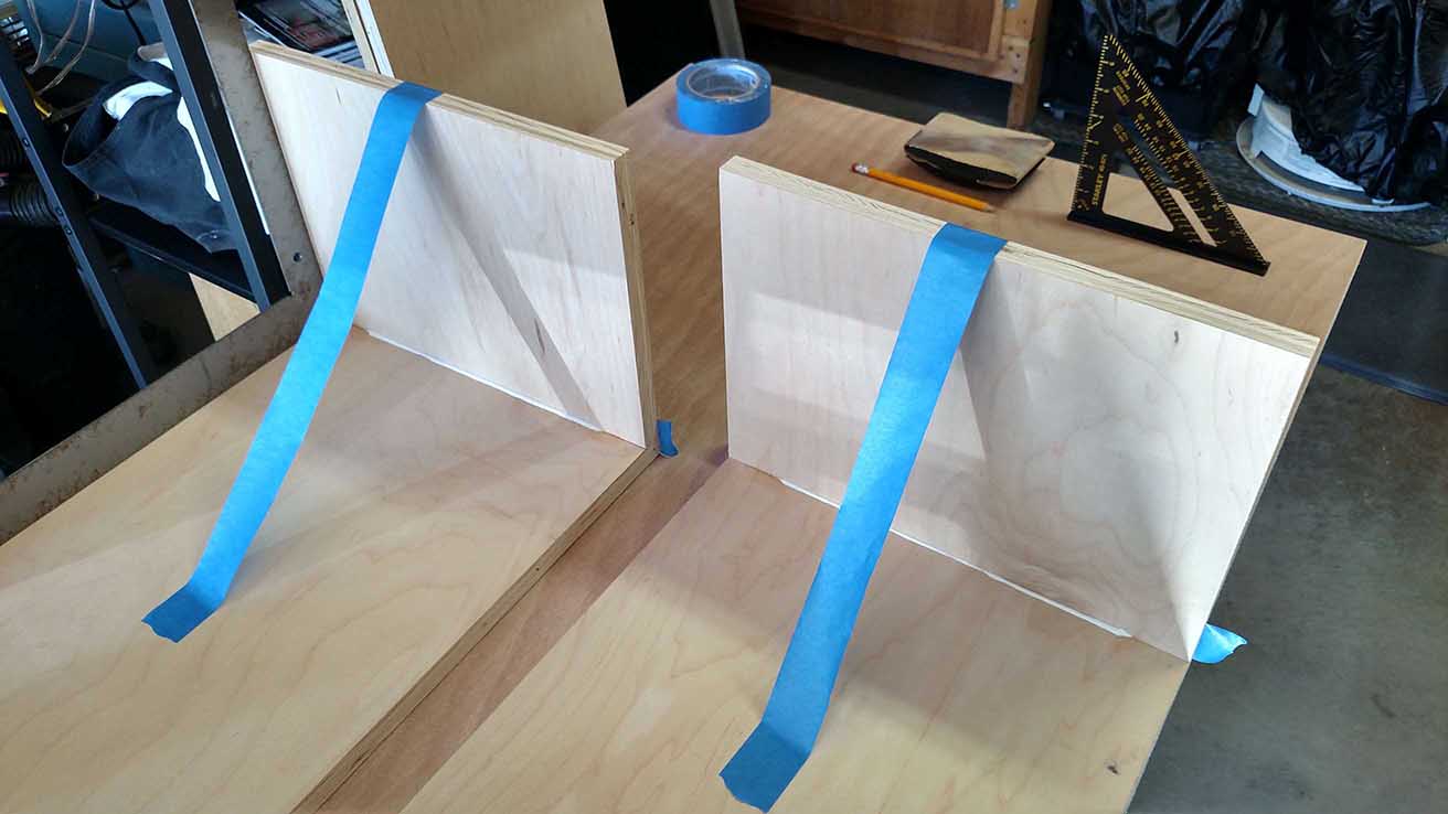
To utilize all of the speakers, I chose a 4-way design with a 5 driver layout having a mid-woofer at the top followed by a tweeter, a mid-range and then dual woofers. For improving the cabinet, I used beveled joints at the top, not butt joints as I had in my first tower build.
Enclosure Assembly:
I used ¾” five ply walnut vineer plywood with cabinet dimensions of 40”H x 11”W x 14”D. I first ripped the plywood sheet on my table saw. Then, I used my radial arm saw to cut the cabinet pieces to the approximate lengths leaving some extra to be trimmed after I cut and dry fit the angles.
I cut the angles using the table saw. Wood glue was used to secure the sides and tops. I used painters tape to keep the pieces square while they dried. A tip for doing this: lay the top and side beveled edge pieces together flat. Place some painters tape along the edge where the two edges meet. Then apply the glue and fold the top up 45°. The tape acts as a hinge. Use a square to get the side perfect, then use tape to secure and let set until the glue dries.
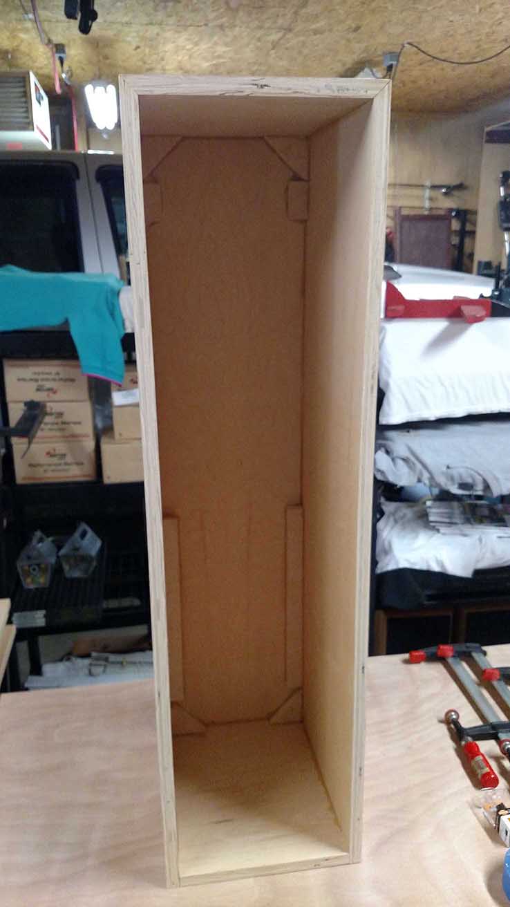
Wood glue was used to assemble the sides and back. Using liquid nails, I installed battens to the inner seems to hold, seal and increase the cabinet strength. I also cut small triangular pieces and secured them in the corners for added strength. I added several more later after the mid-woofer and mid-range/tweeter compartments were completed. This provided additional strength to the enclosure and surface area for gluing the front baffle to the cabinet.
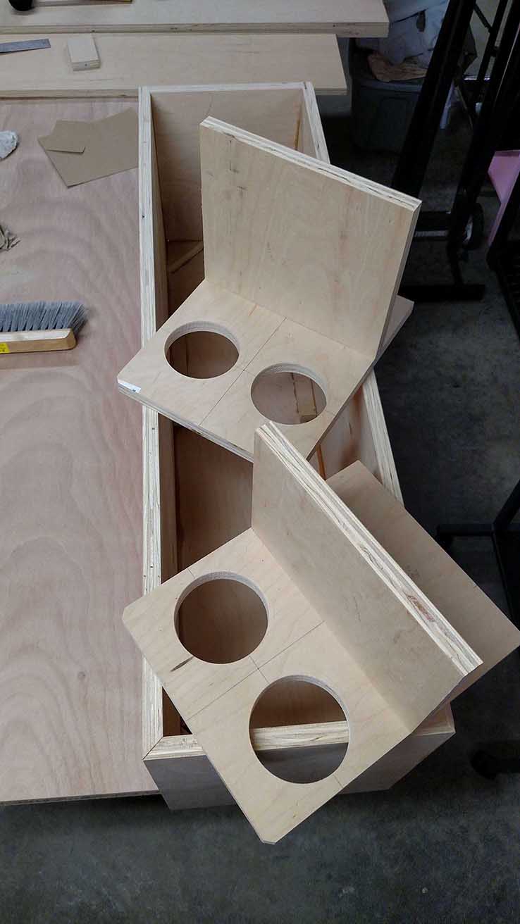
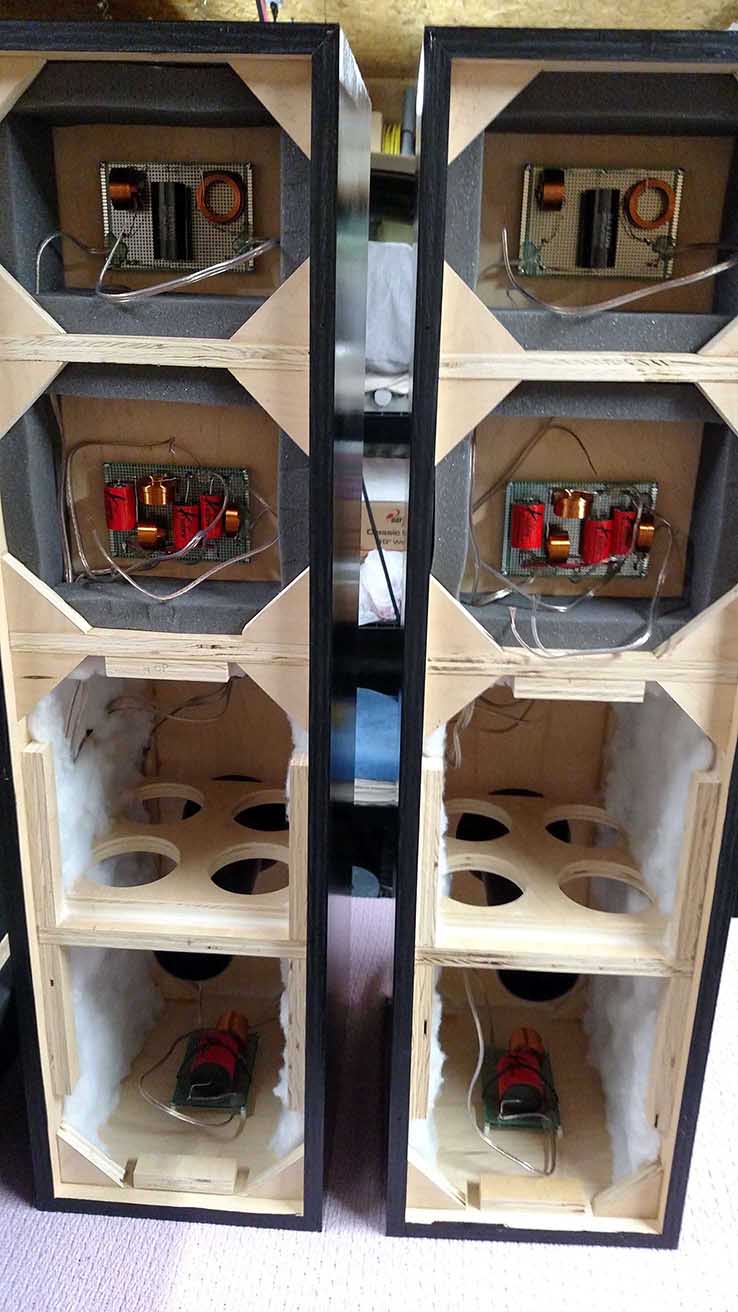
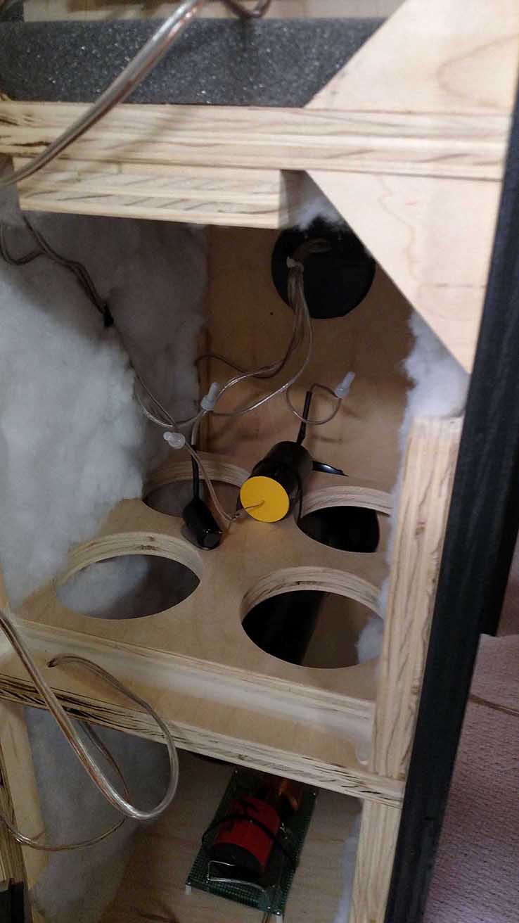
For the mid-woofer and mid-range/tweeter speakers, I created sealed upper compartments. The volume of these compartments did not require porting. Two large holes were cut in each of the lower portions of the compartment walls to allow the space behind them to become part of the volume for the woofers.
Before gluing into place, I lined the walls behind these holes with acoustic dampening polyfill. A brace was added in the woofer compartment connecting the cabinet side walls to further increase strength and to reduce cabinet vibrations. Additional triangle braces and battens were added for support and for gluing surface area of the front baffle. Note that the comparments and triangular support pieces were set 3/4” below the top of the sides to allow for flush mounting the double thick front baffle.
All of the speakers were flush mounted. I used the Jasper Circle Jig model 200 and a router for cutting the precision holes. Parts Express sells this jig and has a very good demonstration video of this jig in action on its web site. I carefully determine the layout of the drivers on the front baffle and after I made several practice cuts in scrap wood using the jig, I began cutting the holes. When cutting, be sure to allow for the speaker edge width and thickness as well as the depth. PE typically provides these dimensions in the speaker literature or you can usually find the specification drawings from the driver manufacturer linked within the PE e-catalog. I measured the actual speakers and looked at the specs, set the router bit accordingly and ran a few test cuts.
Since the baffles were double thickness, I had to cut holes in four pieces of wood, then secure the pieces together. This was done with wood glue and wood screws. Notice the inside baffle is set in ¾”. This area will be glued to the battens and triangular pieces making for a very strong and low vibration front baffle.
After the front baffles were assembled, I dry fit the speakers. Some small adjustments were needed to allow the speakers and wire terminals to set just right. Sandpaper and hand files were used to make these small adjustments.
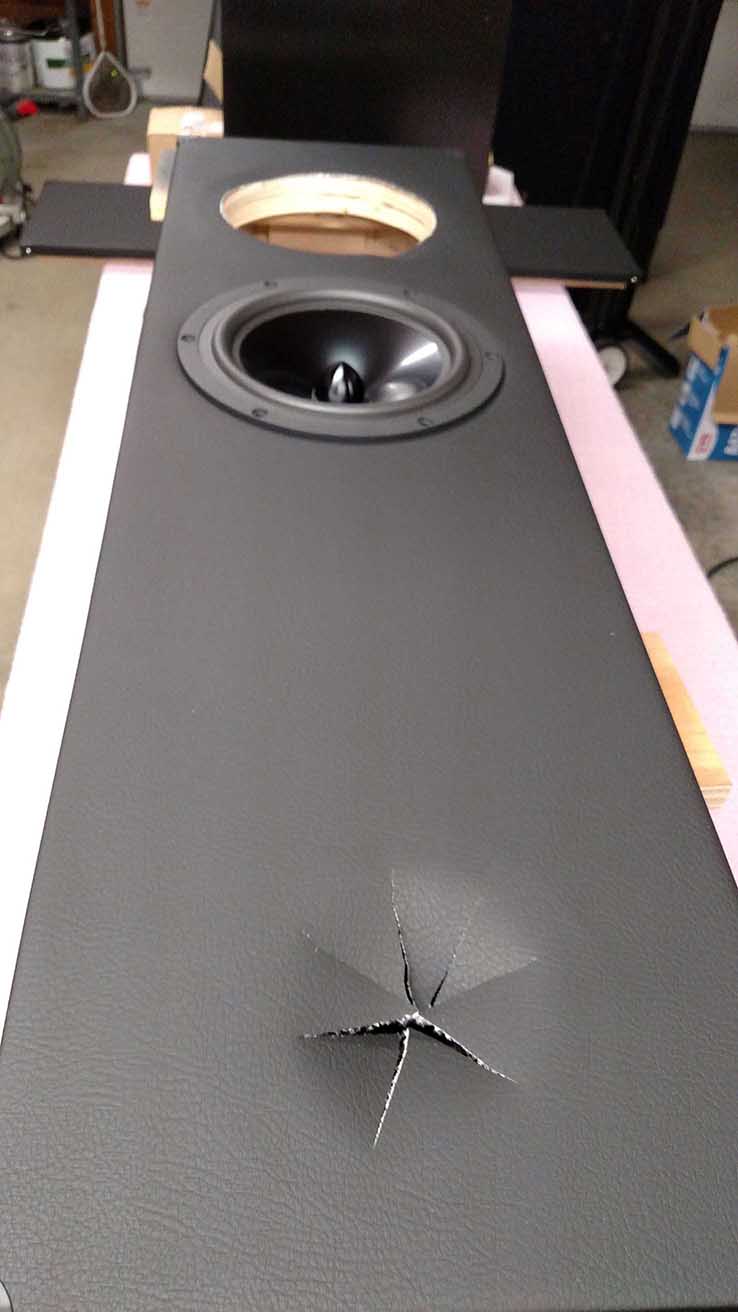
I covered the front baffles in a black vinyl imitation leather material, something that I had seen and liked on some high end speakers. I took into account the thickness of this covering material when cutting the speaker holes.
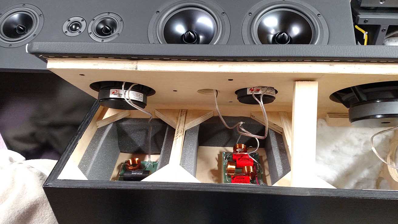
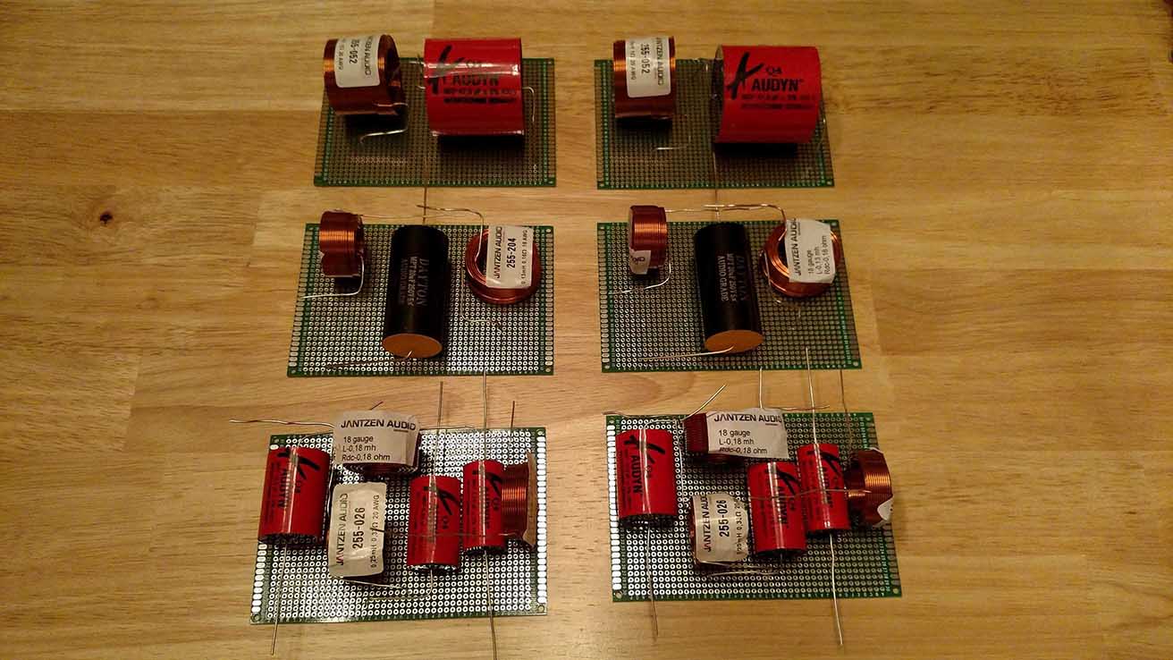
Due to the design being a 4-way and the cabinets having individual closed compartments, I determined it would be best to build the woofer and mid-woofer crossovers separately but combine the mid-range and tweeter crossover onto one board. Then mount each board in the individual compartments. I purchased some DIY FR4 pre-drilled circuit boards from Amazon. These worked as a perfect base for constructing the crossovers. Standard 16 gauge speaker wire was soldered to each of the driver connections on the crossover. For mounting the circuit boards, I used 1” wall anchors cut in half as standoffs and wood screws for mounting. Small holes were drilled for routing the wires to the upper compartments.
I had to modify the mid-woofer crossover near the end of the build when, during listening tests, I found the mid-woofer did not like the low frequencies ≤600hz and was distorting badly. I rectified this by blocking those frequencies with a filter placed in front of the crossover (C4 and L4). Having already completed and mounted the mid-woofer crossover, I mounted this filter in the woofer compartment and wired it between the terminal conections and the mid-woofer crossover. It worked well, completely eliminating the distortion.
Acoustic dampening materials – Polyfill was stapled to the inside walls of the cabinet, the back of the driver baffle and inside the area behind the mid-woofer, midrange and tweeter enclosures before gluing and sealing those compartments. Fixed cell foam material was also added to the mid-woofer and midrange/tweeter compartments to further reduce and dampen unwanted low frequency vibrations.
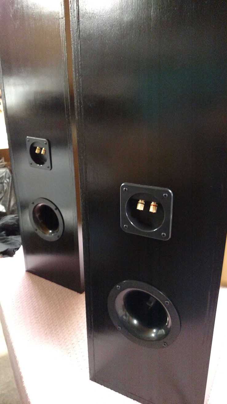
Tuning Port – The tuning port is located on the back of the cabinet. Matt at PE calculated the port size. I provided him with the woofer cabinet volume and the part number of the woofers. Matt determined a 3 inch diameter 9.5 inch long flared port would provide a tuning frequency of 28 hertz.
Wood finish – I wanted the cabinets to be black. So, I applied two coats of black paint to the cabinets and a clear coat of Minwax polyurethane sealer a few days later.
Speaker installation, wiring and final assembly – The drivers were carefully positioned on each of the front baffles and pilot holes drilled for the screws. A hand screw driver was used to install the screws. More control of screw pressure is achieved by hand tightening vs using an electric drill. One slip with a drill driver and a speaker or the vinyl on the baffle could have been ruined. Each driver connection was soldered. Liquid Nails was used for gluing the baffles, side walls, back wall and all other support pieces. Ten large clamps were used to hold the units while the glue hardened. Custom made speaker spike support bars have been constructed but not yet installed.
Crossover Design:
For my first tower project, I had purchased a pre-assembled 3-way crossover. For this project, I wanted to design and build the crossover myself. Since these speakers will be used with a vintage stereo integrated amplifier without a subwoofer connection, the design is a 4-way.
I studied the spec sheets for all of the DA drivers I had purchased and I choose the following crossover points based on the frequency response for each driver:
• Woofer low pass <600hz
• Mid-woofer band pass 600hz – 2.6khz (originally was low pass ≤2.6khz but changed during listening tests)
• Midrange band pass 2.6khz – 6.0khz
• Tweeter high pass >6.0khz
I used several “freeware” and “app” crossover calculators as well as the Parts Express crossover tables to determine the crossover component values.
Conclusion:
I was very happy with the final product. The sound quality and bass greatly exceeded my expectations. On the construction end, the enclosures are very solid and cabinet astetics are much improved verses my first tower build (see “4 Driver, 3 – Way Floor Standing Tower Speaker” in the PE project gallery). The vinyl material on the front baffels provide a very nice and asteticly pleasing appearance. The black finish matches my other home theater components. Currently the speakers are connected to to a Russound two input, 6 speaker out speaker switch so I can run them through the vintage amp and my AV receiver.
About the Designer:
Since my teenage years, I have been interested in electronics, specifically stereo equipment, speakers, amps, etc. I still use my 1978 integrated amplifier as my primary audio source for playing CDs and vinyl. I like the simplicity of the vintage equipment along with the sound and build quality, real aluminum knobs, aluminum face plates, the feel of quality. The pursuit of better quality is what drove me to try my hand at building speakers. Thank you Parts Express for your support in this hobby.
Parts Used:
Jantzen Audio 0.15mH 20 AWG Air Core Inductor Crossover Coil 255-022
Jantzen Audio 0.25mH 20 AWG Air Core Inductor Crossover Coil 255-026
Jantzen Audio 0.40mH 20 AWG Air Core Inductor Crossover Coil 255-032
Jantzen Audio 1.5mH 20 AWG Air Core Inductor Crossover Coil 255-052
Jantzen Audio 0.13mH 18 AWG Air Core Inductor Crossover Coil 255-204
Jantzen Audio 0.18mH 18 AWG Air Core Inductor Crossover Coil 255-208
Clearance 1.0mH 20 Gauge Ferrite Core Inductor 269-2124
Audyn Cap Q4 4.7uF 400V MKP Metalized Polypropylene Foil Capacitor 027-114
Audyn Cap Q4 6.8uF 400V MKP Metalized Polypropylene Foil Capacitor 027-116
Audyn Cap Q4 10uF 400V MKP Metalized Polypropylene Foil Capacitor 027-118
Audyn Cap Q4 47uF 400V MKP Metalized Polypropylene Foil Capacitor 027-122
Dayton Audio DMPC-20 20uF 250V Metalized Polypropylene Capacitor 027-436
Dayton Audio DMPC-40 40uF 250V Metalized Polypropylene Capacitor 027-442
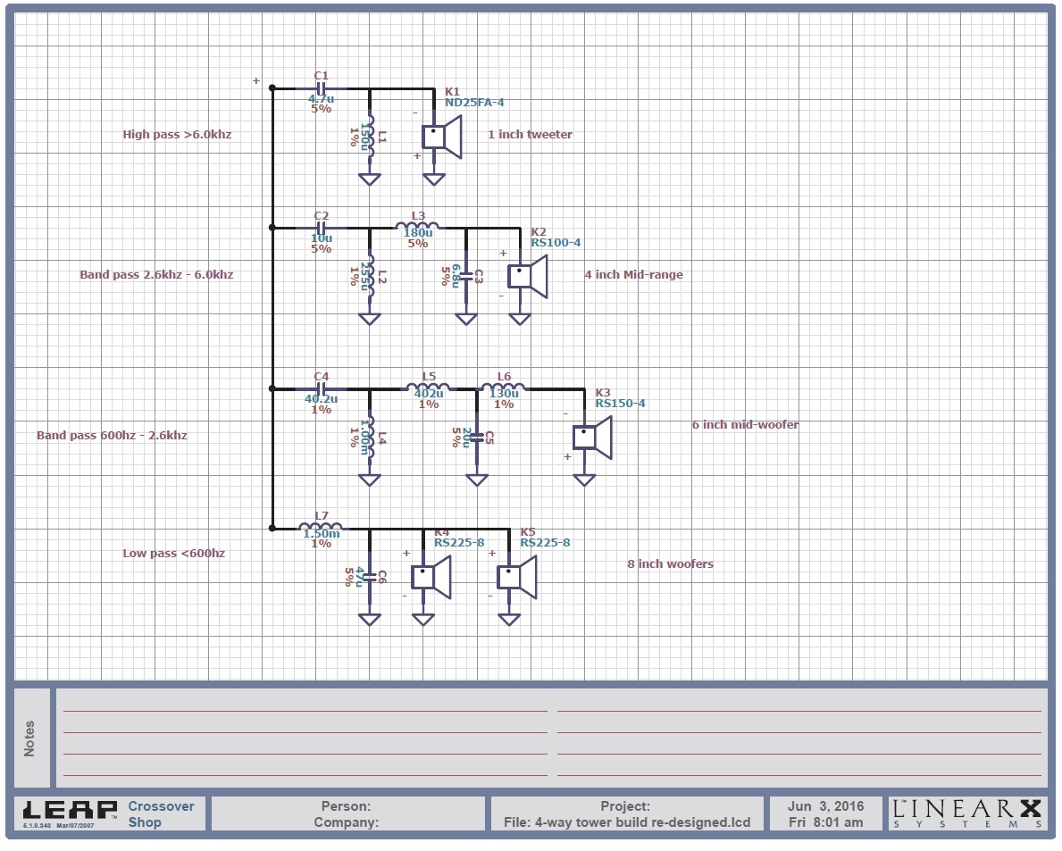
Can you show a detailed wiring diagram? How did you wire 5 speakers to a 4 way crossover?
Hi Frank. Thanks for your question. I have provided a wiring diagram in the image gallery for this project. The two woofers are wired in parallel to the low pass filter. The component values are also shown on the diagram.
I am looking for a speaker project for my home theater, will this speaker perform well in that environment?
Hi Adrian. Thanks for your interest in the Maverics. I am currently using these speakers with my home theater system as the primary front left and right speakers in a 5.1 surround system. I think they sound great with my setup. I am running them with a Pioneer VSX-45 AV receiver. I also have them connected to a “2 amp in, 6 speaker out” speaker switch and I switch them back and fourth between my vintage 1978 stereo amplifier when I listen to cd’s and vinyl and the AV receiver for TV. I couldn’t be more pleased with the sound of these speakers. I absolutely love them. I named them the Maverics because they are a little different, being a 4-way and having a midwoofer at top. If you decide to build I would love to see some pictures. Good luck. Thanks again.
Mike, Thanks for your feedback . What are you using for the center channel? Did you test this speaker as a center?
I did not test this as a center channel. I am using a Polk two way center channel, a pair of Klipsch bookshelfs for the rears and a Kenwood sub. I have thought about building a center channel and two bookshelf speakers using the Dayton Audio Reference series speakers to match these towers.
Hi, I was looking at the components for the crossover and saw that you had listed the “Dayton Audio DMPC-40 40uF 250V Metalized Polypropylene Capacitor 027-442” as a part. Is that required? I didn’t see it on the wiring diagram.
Hi Chris. Thanks for your question. In the wiring diagram, C4 is supposed to a 40uF cap. I have it shown incorrectly as 20uF. Thanks for pointing this out. I had to add C4 and L4 after listening tests. The 40uF cap is shown in picture #13.
Thanks for getting back to me Mike. I’m looking at building a set of speakers similar to yours. Could you tell me the dimensions that used for the individual speaker compartments if you don’t mind? I see that you listed the overall dimensions for the speaker.
Chris: I am very sorry for the reply delay. For some reason my replies on this site have not been going through. I have tried replying several times. I have been in contact with PE tech support trying to fix the issue. The mid-woofer interior dimensions are approximately 9.5″ wide x 8″ tall x 6″ deep. The midrange/tweeter inside dimensions are approximately 9.5″ wide x 8″ tall x 4″ deep. The balance of the interior volume goes to the two woofers including the space behind the boxes. This area is also lined with polyfill. I used the same wood stock for the interior boxes and support pieces which are all 3/4″ thick. I am planning to post some additional interior build photos soon at http://www.mrgigawatt.webs.com. Follow the DIY tab. Thanks and let me know if you need more information.
Mike
Do you have the inside plans with dimensions for the 4 driver 3 way system you built. I cant figure out the location for the bracing. I cant wait to build those!
Bob: Yes, I have the dimensions posted at http://www.mrgigawatt.webs.com along with additional build photos. When you get to the site, click on the DIY tab. The information is there. I would love to hear how your version turns out. Thanks for your interest and good luck with your project.
Do you have any plans for the cabs I really like to copy your build TY much Ken
Ken: I currently do not have detailed drawings of the cabinets but I am working to put those together. I have recently posted additional information that contains many more build photos on my website http://www.mrgigawatt.webs.com. You may be able to closely estimate some of the dimensions from the images. I plan to post the drawings there as well as soon as I complete them. Thanks for your interest and I would love to see your version when completed.
Thank you
Thanks, Mike. I will be sure to check out your additional build photos and maybe post when I am finished with my build. I am in the process of a building a solid state amp and want to finish that first.
Amazing stuff !!!! Do you provide a blueprint for the frame? Thanks . Michel
Bonjour j’habite en France et je serai intéressé par la construction d’une paire d’enceinte pourriez vous me faire parvenir les plans de la menuiserie avec les dimensions . Merci beaucoup .
Due to unavailability of the 1.0mH 20 Gauge Ferrite Bobbin core inductor , i wonder what will be a good replacement ?
_ 2.0 mH 22 or Dayton Audio1.0 mH18 AWG . Thanks
Du to unavailability of 1.0 H 20 Gauge Ferrite, i wonder what will be a good replacement?
– 2.0 mH22 Gauge or Dayton Audio 1.0 mH 18 AWG I core inductor Crossover coil 257-550. Thanks.
For only your 2nd set of speakers, these are mighty nice. GREAT JOB!!!
Pete, thank you very much. I listen to them every day. Stay safe.
Nice build!!!!
How i wish to listen it.
Te saludo desde Colombia, leo tu artículo y me encanta realmente pienso igual con respecto a lo simple pero eficiente, hoy tengo un proyecto más tipo cacero y es recuperar unos parlantes que según lo que he visto las cajas que los contienen no tienen las dimensiones adecuadas y aunque son equipos genéricos me gustaría guiarme por tu proyecto ya veo las dimensiones de tu caja y se acoplan mucho a lo que quiero hacer aunque lo que quiero hacer se reduce a una sola torre como columna principal y con otros paralntes adicionales hacer una barra de sonido que complemente. Toda la eficiencia.
Creerías tu qué me podrías asesorar si te envío lo que tengo pensado?
Looking at a sim of your XO, it looks like you could do a few things to sig. improve your FR (from +/-4dB, to better than +/-2dB).
1st, your woofs & midbass seem to cross higher than you intended, up near 1kHz. Adding +40uF MORE to the 47uF cap should help pull that down. (I’d just try 40uF of cheap (npe) capacitance in parallel w/ your 47.)
Then, both your mid and midbass end up being louder than your tweeter.
By adding a 1ohm resistor (at LEAST 10w, 20 would be better) out in front (amp side) of your bandpass on the RS150, you can tame it a bit.
On your 4″ mid, do the same thing (+ a 1ohm resistor out in front of your series (10uF) cap). Also, it looks like THAT driver’s “breakup” (metal cone “ringing”) up at 13k is interfering with your tweeter’s top end.
You can “notch” that ringing out by jumpering a 4ohm resistor inline w/a TINY 0.68uF cap across the smallest (0.18mH) coil.
Total co$t? – about $10!
Good listening.
Hi Mike, What is the tower speaker impedance in Ohms ? Thanks and Regards.
6 ohms. Thanks
Could you provide more information about “breakup” (metal cone “ringing”) up at 13k ?
Thanks,
gs