ZDT 3.5

Designer: John Krutke
Project Time 8-20 hours
Project Complexity hobbyist
Project Cost $500-$1000
Enclosure Design
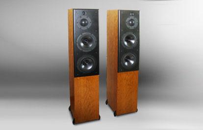
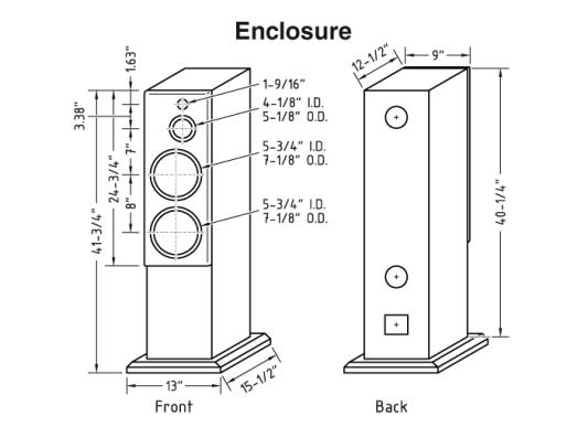
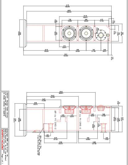
This is a slim ported tower enclosure with a 9″ wide cabinet. It’s pretty obvious that the old and large 3-way cabinet styles from the 60s, 70s, and 80s are no longer popular, and with good reason- nobody wants big “monkey coffins” in their living room anymore, myself included. The enclosure is a three-chamber design, the same one I’ve used for several projects. Removable baffles are a beautiful thing! The lower chamber is empty, perfect for filling with sand or placing the crossover, while that chamber’s height can vary to match a tweeter’s required listening placement. The divider between the upper and lower woofer is not required for clean system operation, but it does add rigidity to the enclosure. Each woofer resides in a .69 cubic ft. (19.5 l) enclosure and may be tuned to 41, 46, or 51 Hz using Parts Express’ 1-1/2″ ID x 4″ L port #260-402 cut to a 100, 85, or 75 mm length respectively.http://zaphaudio.com/ZDT3.5-enclosure.pdf CAD drawing of speaker design.
Amplifier/Crossover Configuration
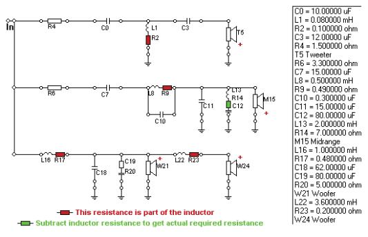
The crossover is 2nd order at 850 and 4th order at 3,500; the midrange and tweeter are wired in phase with each other but out of phase with the woofers. The lower woofer uses a large inductor for baffle step compensation and implements a cascading topology. This means both woofers use the same rolloff components but the lower woofer has an additional component to compensate for the transition from 2pi to 4pi space. Electrically, the woofers are 2nd order with a multi-purpose zobel. The midrange uses a single capacitor for the high pass to reach LR2 along with an impedance-flattening notch to keep the rolloff under control. The midrange low pass uses two components plus a small capacitor shunted across the inductor as a notch filter centered at the dome’s 13 kHz breakup. This not only stamps out the breakup, but also helps us hit a 4th order target with minimal components. The tweeter has a more standard configuration with a low Q 3rd order electrical to achieve the 4th order rolloff. Both the mid and tweeter use a single padding resistor, which simplifies the process of level matching the drivers. All parts for this system are available from Parts Express, and I’ve pre-selected crossover components that will keep the costs down. This includes some electrolytic capacitors for the larger values. The two commonly expressed negatives of electrolytics are lower power handling and degradation over time. In my opinion, electrolytics sound every bit as good as poly, mylar, or metal film capacitors. Some of the electrolytics in this crossover are doubled up for power handling. As far as long-term degradation, if you still have these speakers in 15-20 years then that’s when you’ll have to begin worrying about it. Be aware that three caps are paralleled for C10, to specifically reach .30 uF. Common single cap values such as .22 and .33 will not be a “precision strike” on the mid dome’s breakup node. For resistors, there’s nothing special except that R14 is modified to compensate for the inductor DCR in that circuit, while R20 is doubled up for power handling. L1 in the tweeter circuit is a .08 mH. This value is important, and a .05 or .10 is too far off. Since .08 is an odd size, I’ve specified a Jantzen 20 AWG .10 inductor. It will need 7 turns unwound to reach the .08 value. The turns peel off easily, but you will have to scrape the invisible clear insulation off before soldering into the circuit. For construction of this crossover, I recommend three separate boards. One for the tweeter, one for the mid, and one holds the filter for the upper and lower woofers. Splitting them up will keep things simple and help avoid wiring errors. I also recommend wiring the crossover externally until you’re sure it’s working to your satisfaction. If you seem to be having problems but can’t figure out where, you may need to invest in a Woofer Tester 3 from Parts Express. This is a great impedance checking tool for those who like to build other people’s designs, but aren’t necessarily into extremely complex measurements or crossover design. There are common level tweaking options that will affect the response curve as illustrated, and also make minor changes in the impedance curves. When purchasing your components, at a minimum I recommend getting a few extra resistors to match levels as required for batch consistency or personal preference.
Conclusion
Unlike smaller 2-ways, this system needs a bit more distance for it to sum properly. Because of the relative distances between the drivers, when you’re one meter away from the tweeter you’re also off the axis from the lower woofer at a 30 degree angle, and it’s a few inches further away that affects the phase relationships. It’s not too bad but it does affect the tonal balance. That issue, along with the full baffle step compensation, means this system needs a medium to large room to fit the two and a half meter listening distance. I’d say two meters minimum, but more distance is better. Other than that, there are no special placement requirements other than the normal setup advice I usually give. Keep the back wall, side wall, and floor distances in uneven multiples to achieve the smoothest midbass response. “Thirds” would work well-note the longest boundary dimension; the other two boundary dimensions could be 2/3 and 1/3 of that. This is not a guaranteed method of smoothing room response, but it has a pretty good chance of working. If using these speakers in a home theater setup, allow at least a foot between the speaker and the TV. This is a solid 4 ohm nominal design, so be careful with wimpy low-cost receivers. Impedance drops to 3.2 ohms in the midbass, which is typical for a 4 ohm nominal design. It did seem to work fi ne with an inexpensive Panasonic digital HT receiver, and of course my 120 watts/channel NAD powered it as loud as I could stand. Stay tuned for a center channel option! 3-way and 3.5-way systems are by nature expensive and complicated. Considering that an MTM design with 7″ woofers has the same bass radiating surface and output potential, you may wonder if there really are any good reasons to build a 3.5-way with those drivers. There are two primary benefits: a lower distortion midrange and a smoother upper midrange power response. I think people would be very surprised by how these two factors can present a very different, smooth, and effortless type of sound, particularly when compared to a “typical” MTM configuration. Of course, if you’re on a very tight budget, a simpler MTM- or a TM for that matter, may the better option for you. With this system, I’ve done my best to keep the cost down and the performance high. The wide operating bandwidth of the RS52 dome allowed me to select a low cost tweeter, and keep the woofers operating closer to their optimal range. Multi driver systems like this aren’t for everyone, but if you’ve got the funds, space, and the patience to build and finish the large enclosures, you’ll surely be happy with the results. Enjoy!
About The Designer
John Krutke lives in central Wisconsin with his wife and baby daughter. By day, he is a lead product engineer in the high-speed printing industry. In the evenings, a love of music evolved into a speaker design hobby he has enjoyed for over 20 years. John has designed approximately 50 speaker systems while testing hundreds of drivers in an endless effort to identify the best of them. Some of the fruits of John’s labor can be found on his popular hobbyist website zaphaudio.com.
Project Parts List
|
Part # |
Description |
Qty |
|
275-035 |
Dayton Audio ND20FB-4 Rear-Mount 3/4″ Neodymium Dome Tweeter |
1 |
|
285-020 |
1 |
|
|
295-364 |
1 |
|
|
027-428 |
1 |
|
|
255-020 |
1 |
|
|
027-430 |
1 |
|
|
004-1.5 |
Dayton Audio DNR-1.5 1.5 Ohm 10W Precision Audio Grade Resis |
1 |
|
004-3.3 |
Dayton Audio DNR-3.3 3.3 Ohm 10W Precision Audio Grade Resis |
1 |
|
027-432 |
1 |
|
|
027-358 |
1 |
|
|
255-054 |
1 |
|
|
004-6 |
Dayton Audio DNR-6.0 6 Ohm 10W Precision Audio Grade Resisto |
1 |
|
255-250 |
1 |
|
|
027-344 |
1 |
|
|
027-352 |
1 |
|
|
027-350 |
1 |
|
|
004-10 |
Dayton Audio DNR-10 10 Ohm 10W Precision Audio Grade Resisto |
1 |
|
266-918 |
1 |
|
|
260-402 |
1 |
This design is well documented at his web site.
His web site http://www.zaphaudio.com/ZDT3.5.html has a ton of options for this design.
Lots of other good designs… but his site is really good for it’s driver tests which are many.